Disassembly
Removing and Installing a Processor 2 - 13
2.Disassembly
Processor Installation Procedure
1.
Insert the CPU
(
Figure 9a
), pay careful attention to the pin alignment, it will fit only one way (DO NOT FORCE
IT!), and turn the release latch
towards the lock symbol
(
Figure 9b
).
2.
Remove the sticker
(
Figure 9c
) from the heat sink.
3.
Insert the heat sink
as indicated in
Figure 9d
.
4.
Tighten the CPU heat sink screws in the order r
,
,
, ,,
&
(the order as indicated on the label and
Figure 9d
).
5.
Replace the component bay cover (don’t forget to replace the fan cable) and tighten the screws (
page 2 - 9
).
A
B
C
D
1
2
3
4
5
3
b.
B
a.
D
Note
:
Tighten the screws
in the order as indi-
cated on the label.
C
A
c.
d.
1
2
3
6
5
4
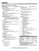
Figure 9
Processor
Installation
a. Insert the CPU.
b. Turn the release latch to-
wards the lock symbol.
c. Remove the sticker from
the heat sink and insert
the heat sink.
d. Tighten the screws.
A. CPU
D. Heat Sink
•
3 Screws
Summary of Contents for W251HNQ
Page 1: ...W251HPQ W251HPQ C W251HNQ W251HNQ C W255HP W255HN W258HPQ W258HPQ C W258HNQ ...
Page 2: ......
Page 24: ...Introduction 1 12 1 Introduction ...
Page 44: ...A 4 Top W255HP W255HN A Part Lists Top W255HP W255HN 灰色 非耐落 Figure A 2 Top W255HP W255HN ...
Page 46: ...A 6 Bottom A Part Lists Bottom Figure A 4 Bottom ...
Page 47: ...SATA BLU RAY COMBO A 7 A Part Lists SATA BLU RAY COMBO 非耐落 志精 Figure A 5 SATA BLU RAY COMBO ...
Page 48: ...A 8 DVD DUAL A Part Lists DVD DUAL Figure A 6 DVD DUAL 非耐落 志精 ...
Page 49: ...LCD A 9 A Part Lists LCD 頭厚 非耐落 中性 Figure A 7 LCD ...
Page 50: ...A 10 A Part Lists ...
Page 103: ...www s manuals com ...