background image

Disassembly

Removing the System Memory (RAM) 2 - 11

2

.D

is

a

s

s

e

m

b

ly

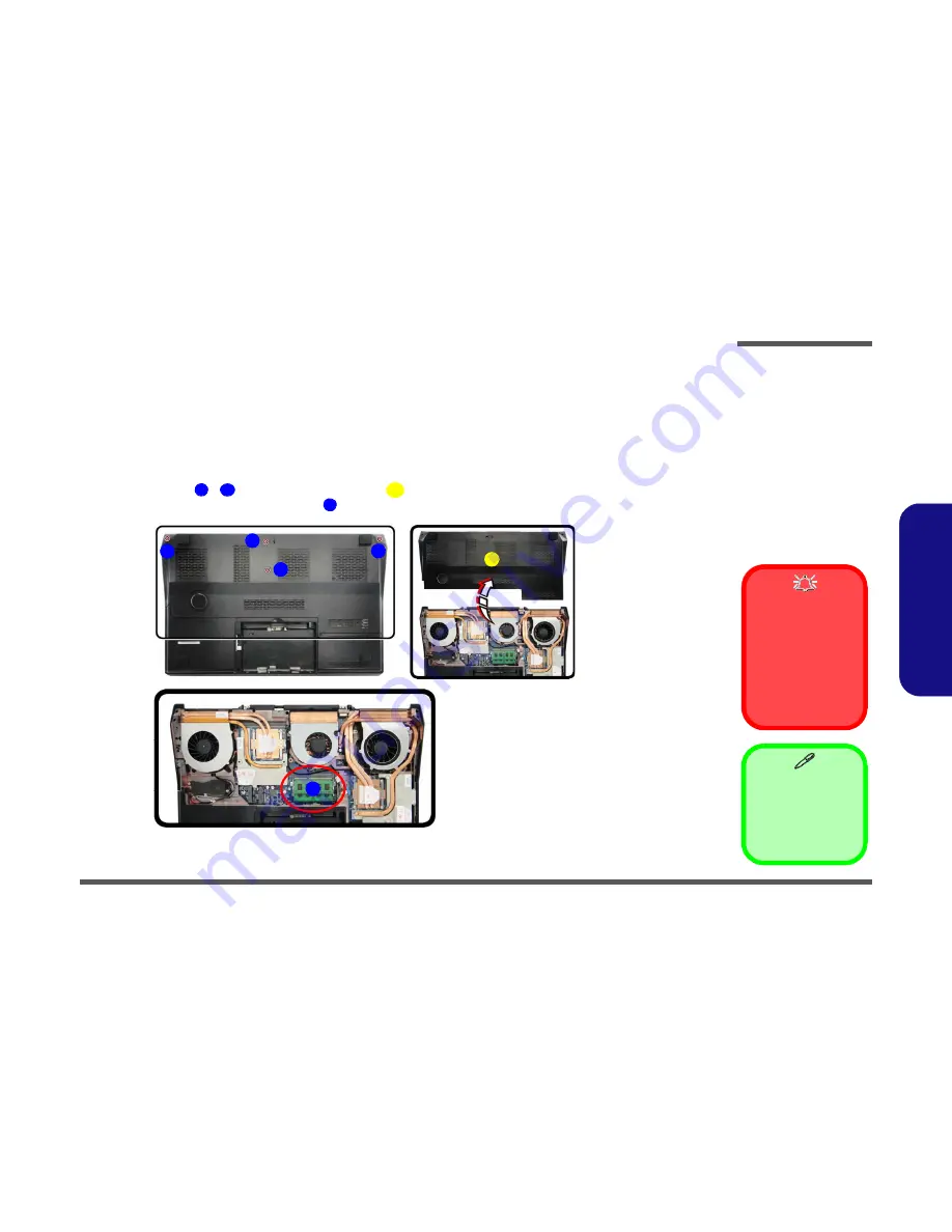
Removing the System Memory (RAM)

The computer has three memory sockets for 204 pin Small Outline Dual In-line Memory Modules (SO-DIMM) DDR III
(DDR3) supporting 1333/1600 MHz. The main memory can be expanded up to 16GB. The total memory size is auto-
matically detected by the POST routine once you turn on your computer. 

Primary System Memory Upgrade Process

1.

Turn off the computer, and turn it over to remove the battery (

page 2 - 5

).

2.

Remove screws 

 - 

 and component bay cover 

.

3.

The RAM module will be visible at point 

 on the mainboard (

Figure 7b

).

Figure 7

 RAM-1 Module 

Removal

a. Remove  screws  and

component bay cover.

b. Locate the module.

5. Component  Bay

Cover

4 Screws

Contact Warning

Be  careful  not to touch
the  metal  pins  on  the
module’s 

connecting

edge.  Even  the  clean-
est  hands  have  oils
which  can  attract parti-
cles,  and  degrade  the
module’s performance.

1

4

5

6

a.

b.

5

1

2

3

4

6

Summary of Contents for P370EM

Page 1: ...P370EM P370EM3 ...

Page 2: ...sassembly process easier each section may have a box in the page margin Information contained under the figure will give a synopsis of the sequence of procedures involved in the disassembly procedure A box with a lists the relevant parts you will have after the disassembly process is complete Note The parts listed will be for the dis assembly procedure listed ONLY and not any previous disassembly ...

Page 3: ...c ing the connection make sure the connector is oriented in the same way The pin1 side is usually not indicated Pressure sockets for multi wire connectors To release this connector type grasp it at its head and gently rock it from side to side as you pull it out Do not pull on the wires themselves When replacing the connection do not try to force it The socket only fits one way Pressure sockets fo...

Page 4: ... Do not pull on the wire 6 Peripherals Turn off and detach any peripherals 7 Beware of static discharge ICs such as the CPU and main support chips are vulnerable to static electricity Before handling any part in the computer discharge any static electricity inside the computer When handling a printed circuit board do not use gloves or other materials which allow static electricity buildup We sugge...

Page 5: ...e battery 1 Turn the computer off remove the AC DC adapter and turn it over 2 Slide the latch in the direction of the arrow and carefully pull the battery up 3 Lift the battery up Figure b and out of the battery bay 3 Battery 1 2 3 3 Figure 1 Battery Removal a Slide the latch and hold it in place b Pull the battery up c Lift the battery out of the bay as indicated a b 1 2 c 3 3 ...

Page 6: ...ur computer Primary System Memory Upgrade Process 1 Turn off the computer and turn it over to remove the battery page 2 5 2 Remove screws and component bay cover 3 The RAM module will be visible at point on the mainboard Figure 7b Figure 7 RAM 1 Module Removal a Remove screws and component bay cover b Locate the module 5 Component Bay Cover 4 Screws Contact Warning Be careful not to touch the meta...

Page 7: ...re 10b 4 Remove screws the reverse order indicated on the label Figure 10c and carefully pull the tabs to disconnect the heat sink 5 Carefully it may be hot lift up the heat sink off the computer Figure 10d Caution The heat sink and CPU area in general con tains parts which are subject to high temper atures Allow the area time to cool before re moving these parts Figure 10 Processor Removal a Loca...

Page 8: ...bel and on the heat sink unit itself 6 Carefully they may be hot remove the heat sink 2 from VGA assembly 6 VGA Heat sink 1 10 VGA Heat sink 2 7 Screws 1 Figure 13 VGA 1 Card Removal a Locate the VGA card b Remove the screws and VGA heat sink 1 c Remove the screws and VGA heat sink 2 2 5 6 7 9 10 a b c 1 6 9 10 4 3 2 5 7 8 Heat Sink Screw Removal and Insertion Remove the screws from the heat sink ...

Page 9: ...etween the master and slave cards do not forget to reconnect the cable if you are replacing two cards 9 Carefully lift the VGA 1 card off the mainboard 11 12 13 14 d e 12 14 11 14 13 13 NVidia VGA Cable AMD VGA Cable Figure 14 VGA 1 Card Removal cont d d Remove the screws and disconnect the VGA ca ble if applicable e Lift the VGA 1 card out 13 VGA Cable 14 VGA 2 Card 2 Screws ...

Page 10: ...on the label and on the heat sink unit itself 6 Carefully they may be hot remove the VGA heat sink 2 6 VGA Heat sink 1 10 VGA Heat sink 2 7 Screws 1 2 5 6 7 9 10 a b 2 c 3 4 5 1 6 7 9 8 10 Heat Sink Screw Removal and Insertion Remove the screws from the heat sink in the order indicated here 7 6 5 4 3 2 1 When tightening the screws make sure that they are tight ened in the order 1 2 3 4 5 6 7 Figur...

Page 11: ...lave cards do not forget to reconnect the cable if you are replacing two cards 9 Carefully lift the VGA 2 card off the mainboard 11 12 13 14 d e 15 13 14 11 12 14 13 13 NVidia VGA Cable AMD VGA Cable Figure 16 VGA 2 Card Removal cont d d Remove the screws and disconnect the VGA ca ble e Lift the VGA 2 card out 13 VGA Cable 14 VGA 2 Card 2 Screws ...

Reviews: