background image

Schematic  Diagrams

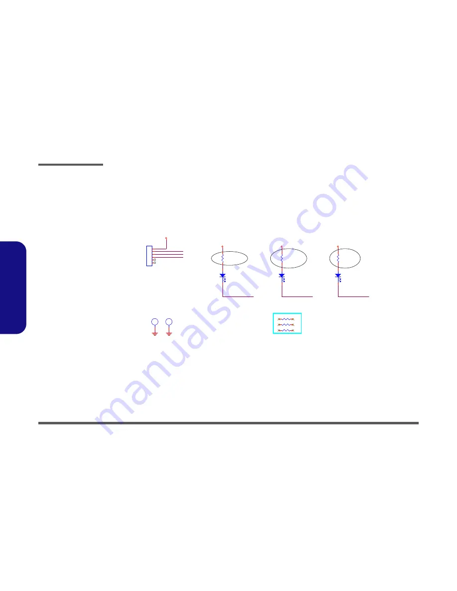
B - 52  P151 LED 3 Board 

B.Schematic Diagrams

P151 LED 3 Board

·s¼W¤uµ{ISSUE

D02A_1219_Alex

D02A_1219_Alex

D02A_1219_Alex

P151SM

L3LED_NUM#

NUM LOCK

LED

1L3R

*0_04

3L3R

*0_04

2L3R

*0_04

L3LED_CAP#

L3LED_NUM#

L3LED_SCROLL#

L3LED_CAP#

CAPS LOCK

LED

L3J_LED1

85201-06051

1

2

3

4

5

6

L3H1
H6_0D2_3

L3H2
H6_0D2_3

L3R1

220_1%_04

L3D1

RY -SP172DNB74-5A

A

C

L3R2

220_1%_04

L3D2

RY -SP172DNB74-5A

A

C

L3R3

220_1%_04

L3D3

RY -SP172DNB74-5A

A

C

L3_3.3VS

L3_GND

L3_GND

L3_3.3VS

L3_3.3VS

L3_3.3VS

L3LED_SCROLL#

SCROLL

LOCK

LED

Sheet 51 of 60

 P151 LED 3 Board

Summary of Contents for p157sm

Page 1: ...P170SM SERVICE MANUAL ...

Page 2: ......

Page 3: ...Preface I Preface Notebook Computer P170SM Service Manual ...

Page 4: ...hole or in part be reproduced translated transmitted or reduced to any machine readable form without prior consent from the vendor manufacturer or creators of this publica tion except for copies kept by the user for backup purposes Brand and product names mentioned in this publication may or may not be copyrights and or registered trademarks of their respective companies They are mentioned for ide...

Page 5: ...servicing and or upgrading components of the P170SM se ries notebook PC The following information is included Chapter 1 Introduction provides general information about the location of system elements and their specifications Chapter 2 Disassembly provides step by step instructions for disassembling parts and subsystems and how to upgrade elements of the system Appendix A Part Lists Appendix B Sche...

Page 6: ... a cordless type during an electrical storm There may be a remote risk of elec trical shock from lightning 3 Do not use the telephone to report a gas leak in the vicinity of the leak 4 Use only the power cord and batteries indicated in this manual Do not dispose of batteries in a fire They may explode Check with local codes for possible special disposal instructions 5 This product is intended to b...

Page 7: ... down properly and don t forget to save your work Remember to periodically save your data as data may be lost if the battery is depleted Do not expose the computer to any shock or vibration Do not place it on an unstable surface Do not place anything heavy on the computer Do not expose it to excessive heat or direct sunlight Do not leave it in a place where foreign matter or mois ture may affect t...

Page 8: ...be sure to disconnect it by the plug head not by its wire Make sure the socket and any extension cord s you use can support the total current load of all the connected devices Before cleaning the computer make sure it is disconnected from any external power supplies Use only approved brands of peripherals Unplug the power cord before attaching peripheral devices Do not plug in the power cord if yo...

Page 9: ...ur hands or metal objects Battery Guidelines The following can also apply to any backup batteries you may have If you do not use the battery for an extended period then remove the battery from the computer for storage Before removing the battery for storage charge it to 60 70 Check stored batteries at least every 3 months and charge them to 60 70 Battery Disposal The product that you have purchase...

Page 10: ...sert the battery and tighten the screws 4 Securely attach any peripherals you want to use with the computer e g keyboard and mouse to their ports 5 Attach the AC DC adapter to the DC In jack at the rear of the computer then plug the AC power cord into an outlet and connect the AC power cord to the AC DC adapter 6 Use one hand to raise the lid LCD to a comfortable viewing angle do not to exceed 130...

Page 11: ...2 Removing the Primary System Memory RAM 2 14 Removing the Secondary System Memory RAM 2 16 Removing the Wireless LAN Module 2 18 Removing the MSATA Module 2 19 Removing and Installing the Processor 2 20 Removing and Installing the Video Card 2 23 Removing the CCD 2 26 Removing the Top Cover 2 27 Part Lists A 1 Part List Illustration Location A 2 Top with Fingerprint A 3 Top without Fingerprint A ...

Page 12: ... Keyboard B 36 mSATA FAN TP FP MULTI CON B 37 Card Reader RTL8411 B 38 USB 3 0 B 39 DDR 1 35V 0 75VS PCH 1 5V B 40 VDD3 VDD5 B 41 5VS 3 3VS 1 5VS B 42 Power 1 05VS B 43 Power V Core 1 B 44 AC_In Charger B 45 TPM B 46 Audio Board B 47 P150 151 ODD Board B 48 P150 151 Click Board B 49 P150 170SM LED 1 Board B 50 P151 LED 2 Board B 51 P151 LED 3 Board B 52 P170 HDD ODD Board B 53 P170 LED Board B 54 ...

Page 13: ...ual is shipped with the computer Operating systems e g Windows 8 etc have their own manuals as do application software e g word processing and database programs If you have questions about those programs you should consult those manuals The P170SM series notebook is designed to be upgradeable SeeDisassembly on page 2 1 for a detailed description of the upgrade procedures for each specific componen...

Page 14: ... two SO DIMMs maximum Core Logic Intel HM87 Express Chipset BIOS AMI BIOS 48Mb SPI Flash ROM Security Security Kensington Type Lock Slot BIOS Password Factory Option Fingerprint Reader Module Storage Factory Option One 12 7mm h Optical Device Type Drive Super Multi Drive Blu Ray Combo Drive Blu Ray Writer Drive Two Changeable 2 5 h SATA Serial Hard Disk Drives HDDs SSDs supporting RAID Level 0 1 F...

Page 15: ...Mini IEEE1394a Port One RJ 45 LAN Jack One DC In Jack Note External 7 1CH Audio Output Supported by Head phone Microphone Line In and S PDIF Out Jacks Communication Built In Giga Base TX Ethernet LAN 2M FHD PC Camera Module WLAN Bluetooth Half Mini Card Modules Factory Option Intel Centrino Ultimate N 6300 Wire less LAN 802 11a g n Factory Option Intel Centrino Advanced N 6235 Wire less LAN 802 11...

Page 16: ... 1 Top View 1 Built In PC Camera 2 PC Camera LED 3 Built In Microphone 4 LCD 5 Speakers 6 LED Indicators 7 Power Button 8 Illuminated Keyboard 9 TouchPad and Buttons 10 Fingerprint Reader Optional 3 2 1 8 9 7 6 5 4 5 10 Note tha t the Touchpad a nd Buttons has a valid operation al area ind icated w ithin the red dotted lines above ...

Page 17: ...duction External Locator Front Right side Views Figure 2 Front Views 1 LED Power Indicators Figure 3 Right Side Views 1 Optical Device Drive Bay 2 Emergency Eject Hole 3 Headphone Jack 4 Microphone Jack 5 S PDIF Out Jack 6 Line In Jack 7 USB 2 0 Port 1 1 3 4 2 7 5 6 ...

Page 18: ...re 4 Left Side View 1 Mini IEEE 1394a Port 2 RJ 45 LAN Jack 3 USB 3 0 Port USB Charge 4 USB 3 0 Port 5 Combined eSATA Powered USB 3 0 Port 6 Multi in 1 Card Reader 1 2 4 5 6 3 Figure 5 Rear View 1 Vent Fan Intake 2 Display Port 3 HDMI Out Port 4 Mini Display Port 5 DC In Jack 6 Security Lock Slot 2 3 5 1 4 1 6 ...

Page 19: ...tom View Figure 6 Bottom View 1 Sub Woofer 2 Fan Outlet Intake 3 Component Bay Cover 4 Primary HDD Bay 5 Secondary HDD Bay 6 Battery Overheating To prevent your com puter from overheating make sure nothing blocks the vent fan in takes while the com puter is in use 1 2 4 5 3 2 2 2 6 ...

Page 20: ...Introduction 1 8 Mainboard Overview Top Key Parts 1 Introduction Mainboard Overview Top Key Parts Figure 7 Mainboard Top Key Parts 1 Platform Controller Hub 2 Audio Codec 3 KBC ITE IT8587 1 2 3 ...

Page 21: ...m Key Parts 1 9 1 Introduction Mainboard Overview Bottom Key Parts Figure 8 Mainboard Bottom Key Parts 1 VGA Card Connector 2 CPU Socket no CPU installed 3 Memory Slots DDR3 SO DIMM Primary 4 Hard Disk Connector 5 MSATA Connector 5 2 1 4 3 ...

Page 22: ... 12 Figure 9 Mainboard Top Connectors 1 USB 3 0 Port e SATA 2 Multi in 1 Card Reader 3 KB LED Connector 4 TP LED Cable Connector 5 LED 4 Cable Connector 6 TouchPad Cable Connector 7 MSATA Cable Connector 8 LED 3 Cable Connector 9 Keyboard Cable Connector 10 Audio Cable Connector 11 LCD Cable Connector 12 eDP Cable Connector ...

Page 23: ...view Bottom Connectors Figure 10 Mainboard Bottom Connectors 1 DC In Jack 2 Mini Display Port 3 HDMI Out Port 4 Display Port 5 VGA Fan Cable Connector 6 Sub Woofer Cable Connector 7 CPU Fan Cable Connector 8 USB 3 0 Ports 9 RJ 45 LAN Jack 10 Mini IEEE 1394a Port 1 2 3 4 5 6 7 8 9 8 10 ...

Page 24: ...Introduction 1 12 1 Introduction ...

Page 25: ...embly process easier each section may have a box in the page margin Information contained under the figure will give a synopsis of the sequence of procedures involved in the disassembly procedure A box with a lists the relevant parts you will have after the disassembly process is complete Note The parts listed will be for the dis assembly procedure listed ONLY and not any previous disassembly step...

Page 26: ...ing the connection make sure th e connector is oriented in the same way The pin1 side is usually not indicated Pressure sockets for multi wire connectors To release this connector type grasp it at its head and gently rock it from side to side as you pull it out Do not pull on the wires themselves When replacing the connection do not try to force it The socket only fits one way Pressure sockets for...

Page 27: ...o not pull on the wire 6 Peripherals Turn off and detach any peripherals 7 Beware of static discharge ICs such as the CPU and main support chips are vulnerable to static electricity Before handling any part in the computer discharge any static electricity inside the computer When handling a printed circuit board do not use gloves or other materials which allow static electricity buildup We suggest...

Page 28: ...ve the Optical device page 2 10 3 Remove the HDD page 2 12 To remove the Primary System Memory 1 Remove the battery page 2 5 2 Remove the system memory page 2 14 To remove the Secondary System Memory 1 Remove the battery page 2 5 2 Remove the keyboard page 2 16 3 Remove the system memory page 2 16 To remove the WLAN Module 1 Remove the battery page 2 5 2 Remove the keyboard page 2 16 3 Remove the ...

Page 29: ...gure 1a 3 Slide the latch in the direction of the arrow and hold it in place Figure 1a 4 The battery may be levered up at point Figure 1b 5 Lift the battery out of the compartment Figure 1c 4 Battery 1 2 3 6 4 a b 2 1 4 c 3 1 2 Figure 1 Battery Removal a Slide the latch and hold in place b Slide the battery out in the direction of the arrow c Lift the battery out ...

Page 30: ...over and remove screws Figure 2a 3 Remove the hard disk bay cover by levering the cover at point Figure 2b Figure 2 HDD Assembly Removal a Locate the HDD bay cover and remove the screws b Remove the hard disk bay cover by levering the cover at point 3 4 Hard Disk Bay Cover 2 S crews 1 2 6 4 3 a HDD System Warning New HDD s are blank Before you begin make sure You have backed up any data you want t...

Page 31: ...rews and the insulation plate Figure 3e 7 Reverse the process to install a new hard disk do not forget to replace all the screws and covers 4 6 5 6 7 6 8 c d 5 6 4 7 e 8 5 HDD 8 HDD Insulation Plate 2 S crews Figure 3 HDD Assembly Removal cont d c Slide the HDD assembly in the direction of the ar row d Remove the hard disk assembly e Remove the screws and the insulation plate ...

Page 32: ...ives In some cases 7mm H hard disk drives will be installed For more information cont act your distributor s upplier and bear in mind your warranty terms Figure 4 Foam Rubber Insert for 7mm H HDDs If you are replacing a 9 5mm H HDD witha 7mm H HDD then insert the foam rubber insert as shown above If you are replacing a 7mm H HDD with a 9 5mm H HDD then remove the foam rub ber insert ...

Page 33: ...e Figure 5a 3 Remove the SSD shielding plate and remove the screw from the SSD Figure 5b 4 The SSD module will pop up and you can remove it from the computer Figure 5c 5 Reverse the process to install a new SSD Figure 5 SSD Removal a Remove the screws b Remove the shielding plate and screw c Remove the SSD mod ule 1 6 2 3 6 4 2 SSD Shielding Plate 4 SSD Module 2 S crews 1 3 2 4 a b 4 c ...

Page 34: ...er and screw at point Figure 6b 4 Use a screwdriver to carefully push out the optical device out of the bay at point Figure 6d 5 Reverse the process to install any new optical CD DVD device Figure 6 Optical Device Removal a Locate the secondary hard disk bay cover and remove the screws b Remove the cover and screw c Push the optical device out off the computer at point 6 1 2 6 3 4 6 5 6 3 Secondar...

Page 35: ...e 7f 9 Insert the new device and carefully slide it into the computer the device only fits one way DO NOT FORCE IT The screw holes should line up 10 Replace the component bay cover and tighten the screws 11 Restart the computer to allow it to automatically detect the new device 8 7 8 8 9 8 Bezel Cover 1 S crew f 8 d e 7 8 9 Figure 7 Optical Device Removal cont d d Pry the bezel off the opti cal de...

Page 36: ...ews from the secondary HDD assembly Figure 8a 3 Slide the secondary HDD assembly in the direction of the arrow it will not move fully out of the bay Figure 8a 4 Lift the secondary HDD assembly up and out of the bay in the reverse direction of the arrow Figure 8c 5 Hard Disk Assembly 3 Screws Figure 8 Secondary HDD Assembly Removal a Remove the screws from the secondary HDD as sembly b Slide the se...

Page 37: ...ll the insulation plate 7 Slide the HDD assembly into the bay at an angle as illustrated 8 Make sure the insulation plate slides under the HDD bay guide at point 9 Slide the assembly in the direction of the arrow and secure the assembly with the screws Figure 9 Secondary HDD Assembly Removal d Remove the screws and the insulation plate 10 HDD Insulation Plate 11 HDD 4 S crews 6 9 10 11 9 7 6 8 d 1...

Page 38: ... upgradable If you are installing only two RAM modules then they should be installed in the primary memory sockets under the component bay cover Note that the RAMlocated under the keyboard is not user upgradable Contact your service center formore information if you wish to upgrade the memory in the secondary memory sockets Memory Upgrade Process 1 Turn off the computer and turn it over remove the...

Page 39: ...OT FORCE the module it should fit without much pressure 11 Press the module in and down towards the mainboard until the slot levers click into place to secure the module 12 Replace the bay cover and screws 13 Restart the computer to allow the BIOS to register the new memory configuration as it starts up 6 9 10 Figure 11 RAM Module Removal cont d d Lift the component bay cover off the computer case...

Page 40: ...ay cover page 2 14 2 Remove the top cover module Figure 12a 3 Remove screws Figure 12a 4 Carefully lift the keyboard up being careful not to bend the keyboard ribbon cable Figure 12c Figure 12 RAM Module Removal a Remove the top cover module b Remove the screws c Carefully lift the key board up being careful not to bend the keyboard ribbon cable A 1 5 B 6 A Top Cover Module B Keyboard 5 S crews a ...

Page 41: ...e slot as it will go DO NOT FORCE the module it should fit without much pressure 12 Press the module in and down towards the mainboard until the slot levers click into place to secure the module 13 Replace the bay cover and screws 14 Restart the computer to allow the BIOS to register the new memory configuration as it starts up 6 7 8 9 Figure 13 RAM Module Removal cont d e Disconnect the key board...

Page 42: ...Carefully disconnect cables then remove screw from the module socket Figure 14b 4 The Wireless LAN module will pop up Figure 14c 5 Lift the Wireless LAN module Figure 14d up and off the computer Figure 14 Wireless LAN Module Removal a The Wireless LAN mod ule will be visible at point under the keyboard b Disconnect the cables and remove the screw c The WLAN module will pop up d Lift the WLAN modul...

Page 43: ...cover page 2 14 2 Locate the module it is visible at point Figure 15a 3 Carefully remove the screw from the module Figure 15b 4 Lift the module up and off the computer Figure 15b Figure 15 MSATA Module Removal a Locate the module b Remove the screw c The module will pop up d Lift the module up off the socket 1 2 3 a b 1 3 2 3 c d 3 MSATA Module 1 S crew ...

Page 44: ... screw 4 first through to screw 1 last Figure 16a 3 Carefully it may be hot remove the heat sink unit Figure 16b 1 4 5 Figure 16 Processor Removal Procedure a Remove the screws in the correct order b Carefully remove the heat sink unit CPU Warning In order to prevent damaging the contact pins when removing the CPU it is neces sary to first remove the WLAN module from the computer 5 Heat Sink Unit ...

Page 45: ...formation on inserting a new CPU 7 When re inserting the CPU pay careful attention to the pin alignment it will fit only one way DO NOT FORCE IT 6 A Figure 17 Processor Removal cont d c Turn the release latch to unlock the CPU d Lift the CPU out of the socket Caution The heat sink and CPU area in general contains parts which are subject to high temperatures Al low the area time to cool before re m...

Page 46: ...nsert the heat sink unit as indicated in Figure 18c 4 Tighten the CPU heat sink screws in the order the order as indicated on the label and Figure 18d 5 Replace the CPU fan component bay cover and tighten the screws page 2 20 A B C D 1 2 3 4 c b d B a C D 1 4 2 Note Tighten the screws in the order 1 2 3 4 as indicated on the label 3 A Figure 18 Processor Installation a Insert the CPU b Turn the re...

Page 47: ...gure 19d 8 Heat Sink Unit 11 Video Card 9 S crews Caution The heat sink and video card area in general contains parts which are subject to high tempera tures Allow the area time to cool before re moving these parts Figure 19 Video Card Removal Procedure a Remove the screws in the correct order b Carefully remove the heat sink units c Remove the video card screws The video card will pop up d Remove...

Page 48: ...l procedure 6 Remove screws from the video card assembly Figure 20e 7 Separate the shielding plate from the video card Figure 19d 11 Video Card 16 Shielding Plate 4 S crews Figure 20 Video Card RemovalProcedure cont d e Remove the screws f Separate shielding plate and video card 12 15 16 11 e 11 f 15 16 13 12 14 ...

Page 49: ...ing DO NOT FORCE the card it should fit without much pressure 6 Secure the card with screws Figure 21 on page 2 25 7 Place the heat sink back on the card and secure the screws in the order indicated in Figure 21 on page 2 25 8 Attach the video card fan and secure with the screws as indicated in Figure 19 on page 2 23 9 Reinsert the component bay cover and secure with the screws as indicated in Fig...

Page 50: ...igure 22b 4 Carefully Remove the LCD panel off Figure 22c 5 Disconnect the cable Figure 22d 6 Remove the CCD module off Figure 22e Figure 22 CCD Module Removal a Remove the rubbers and screws b Run your fingers around the inner frame of the LCD panel at the points indicated by the arrow c Remove the LCD panel d Disconnect the cable e Remove the CCD mod ule 1 6 A D 7 8 9 5 b a 2 3 1 9 d c 7 4 6 e B...

Page 51: ... wires at the point from the holder as indicated by the arrows Figure 23a 3 Turn the computer over remove the fan cables and screws Figure 22b 4 Remove the fan unit off the computer Figure 22c 1 3 4 A C 5 6 7 13 14 5 a 2 3 1 c b 4 6 B A C 7 8 9 10 11 14 14 12 13 14 Fan Unit 7 S crews Figure 23 Top Cover Removal a Disconnect the cable connectors and lift the the wires from its holder b Disconnect t...

Page 52: ...eleased from its holder Figure 24f 8 Reverse the process to install the top cover do not forget to replace all the screws hinge cover and bottom case 15 35 36 37 39 38 40 12 13 36 e d f 37 28 15 16 17 18 19 20 21 22 23 35 26 25 24 27 34 33 32 29 30 31 38 40 37 40 39 37 Top Cover 39 Bottom Case 40 Hinge Cover 21 S crews Figure 24 Top Cover Removal cont d d Remove the screws e Lift the LCD panel f S...

Page 53: ...ers Your organization may use a different system so be sure to cross check any relevant documentation Note Some assemblies may have parts in common especially screws However the part lists DO NOT in dicate the total number of duplicated parts used Note Be sure to check any update notices The parts shown in these illustrations are appropriate for the system at the time of publication Over the produ...

Page 54: ...The following table indicates where to find the appropriate part list illustration Table A 1 Part List Illustration Location Parts Top with Fingerprint page A 3 Top without Fingerprint page A 4 Bottom N14E GS page A 5 Bottom N14E GTX page A 6 LCD page A 7 COMBO page A 8 DVD Dual Drive page A 9 ...

Page 55: ...Part Lists Top with Fingerprint A 3 A Part Lists Top with Fingerprint Figure A 1 Top with Fingerprint ...

Page 56: ...Part Lists A 4 Top without Fingerprint A Part Lists Top without Fingerprint Figure A 2 Top without Fingerprint ...

Page 57: ...Part Lists Bottom N14E GS A 5 A Part Lists Bottom N14E GS Figure A 3 Bottom N14E GS ...

Page 58: ...Part Lists A 6 Bottom N14E GTX A Part Lists Bottom N14E GTX Figure A 4 Bottom N14E GTX ...

Page 59: ...Part Lists LCD A 7 A Part Lists LCD Figure A 5 LCD ...

Page 60: ...Part Lists A 8 COMBO A Part Lists COMBO Figure A 6 COMBO ...

Page 61: ...Part Lists DVD Dual Drive A 9 A Part Lists DVD Dual Drive Figure A 7 DVD Dual Drive ...

Page 62: ...Part Lists A 10 A Part Lists ...

Page 63: ...31 P151 LED 3 Board Page B 52 DDRIII CHA SO DIMM_1 Page B 11 RJ 45 Page B 32 P170 HDD ODD Board Page B 53 DDRIII CHB SO DIMM_1 Page B 12 Codec Realtek ALC892 Page B 33 P170 LED Board Page B 54 DDRIII CHB SO DIMM_0 Page B 13 APA2607 TPA2008D2 Page B 34 P170 Click Board Page B 55 MXM PCI E Page B 14 KBC ITE IT8587B Page B 35 P170 Fingerprint Board Page B 56 Panel CRT Page B 15 Backlight Keyboard Pag...

Page 64: ...II INT MIC 25 MHz USB 2 0 1 35V VDDQ 1 5VS Azalia Codec INT K B Lynx Point Controller Hub PCH GEN1 12 GEN2 3 6 mSATA 6 eSATA 12 ITE 8587A 512KB ROM SATA I II III 6 0Gb s 1 05VM 1 05VS 1 05V_LAN_M Realtek rPGA947 VDD3 VDD5 DMI 4 1067 1333 1600 MHz DDR3L 1 35V 12 MHz FingerPrint FINGER PRINTER ON CLICK BOARD P150 Optional PCIE 16 USB4 5 Gbps USB 3 0 Mini PCIE SOCKET USB3 WLAN RTL8411 Charging AUDIO ...

Page 65: ...9 0 22u_10V_X5R_04 C628 0 22u_10V_X5R_04 C76 0 22u_10V_X5R_04 C75 0 22u_10V_X5R_04 C514 0 22u_10V_X5R_04 C77 0 22u_10V_X5R_04 C79 0 22u_10V_X5R_04 C78 0 22u_10V_X5R_04 C367 0 22u_10V_X5R_04 C85 0 22u_10V_X5R_04 C86 0 22u_10V_X5R_04 C620 0 22u_10V_X5R_04 C16 0 22u_10V_X5R_04 C637 0 22u_10V_X5R_04 C91 0 22u_10V_X5R_04 C90 0 22u_10V_X5R_04 C93 0 22u_10V_X5R_04 C94 0 22u_10V_X5R_04 C521 0 22u_10V_X5R_...

Page 66: ...OMP_2 SM_RCOMP_1 SM_RCOMP_0 BUF_CPU_RST H_CPUPWRGD_R BSS138 VGS 1 5V Haswell Processor 2 7 MISC JTAG CLK XDP_TDO_R Processor Pullups Pull downs TRACE WIDTH 10MIL LENGTH 500MILS DDR3 Compensation Signals S3 circuit DRAM_RST to memory should be high during S3 Buffered reset to CPU H_PROCHOT _R PCH_PLTRST_CPU H_PROCHOT H_PROCHOT _R D01a_1009_Alex H_CPUPWRGD_R H_CPUPWRGD FC_AK31 DPLL_REF_CLKN R114 10m...

Page 67: ... A15 SB_DQ_59 B15 SB_DQ_60 E14 SB_DQ_61 D14 SB_DQ_62 A14 SB_DQ_63 B14 SB_DQ_35 M4 SB_DQ_33 M2 SB_DQ_31 AK1 SB_DQ_30 AK2 SB_DQ_29 AN1 SB_DQ_28 AM1 SB_DQ_44 J7 SB_DQ_43 G9 RSVD AG8 SB_CKE_1 AG10 SB_CKE_0 AF10 SB_CKN0 Y4 SB_CKN1 Y3 SB_CKN2 Y2 SB_CKN3 Y1 SB_CKP0 AA4 SB_CKP1 AA3 SB_CKP2 AA2 SB_CKP3 AA1 R495 1K_04 VDDQ M_A_CKE1 9 VDDQ VDDQ M_A_DQS 7 0 9 10 M_A_CS 1 9 M_A_CS 0 9 M_A_CLK_DDR 0 9 M_A_CLK_D...

Page 68: ...P0 R29 DDID_TXP1 P28 DDID_TXP2 R31 DDID_TXN3 N30 DDID_TXP3 P30 FDI_TXP_1 P32 FDI_TXN_1 N32 FDI_TXP_0 R33 FDI_TXN_0 P33 EDP_TXP_1 P34 DDIC_TXP0 U34 DDIC_TXN0 T34 DDIB_TXP3 V31 DDIB_TXN3 U31 DDIB_TXP2 V29 DDIB_TXN2 U29 DDIB_TXP1 U30 DDIB_TXN1 T30 DDIB_TXP0 U28 DDIB_TXN0 T28 VCCIO_OUT iGP_eDP_TX 0 14 iGP_eDP_AUX 14 VCCIOA_OUT 2 6 iGP_eDP_AUX 14 iGP_eDP_TX0 14 iGP_eDP_TX1 14 iGP_eDP_TX 1 14 HDMI_C0N 1...

Page 69: ...E34 VCC AF25 VCC AF26 VCC AF27 VCC AF28 VCC AF29 VCC AF30 VCC AF31 VCC AF32 VCC AF33 VCC AF34 VCC AF35 VCC AG26 VCC AH26 VCC AH29 VCC AH32 VCC AH35 VCC AH27 VCC AH28 VCC AH31 VCC AH33 VCC AH34 VCC AJ25 VCC AJ26 VCC AJ27 VCC AJ28 VCC AJ29 VCC AJ30 VCC AJ31 VCC AJ32 VCC AJ33 VCC AJ34 VCC AJ35 VCC G25 VCC H25 VCC J25 VCC K25 VCC L25 VCC M25 VCC N25 VCC P25 VCC R25 VCC T25 VCC U25 VCC U26 VCC V25 VCC ...

Page 70: ...F 9 U32F VSS B22 VSS B2 VSS B19 VSS B16 VSS B13 VSS B10 VSS AT7 VSS AT4 VSS AT30 VSS AT3 VSS AT27 VSS AT24 VSS AT21 VSS AT19 VSS AT16 VSS AT13 VSS AT10 VSS AR7 VSS AR4 VSS AR34 VSS AR31 VSS AR28 VSS AR25 VSS AR22 VSS AR2 VSS AR19 VSS AR16 VSS AR13 VSS AP4 VSS AP19 VSS AP16 VSS AP10 VSS AP1 VSS AN7 VSS AN4 VSS AN34 VSS AN30 VSS AN27 VSS AN24 VSS AN21 VSS AN2 VSS AN19 VSS AN16 VSS AN13 VSS AN10 VSS ...

Page 71: ... 1K_1 _04 R84 1K_04 R85 1K_04 R708 49 9_1 _04 R706 49 9_1 _04 VCORE 6 7 44 PM_PCH_PWROK 21 VCORE TESTLO_G26 TESTLO_G26 RSVD_W30 CFG9 RSVD_A34 CFG17 RSVD_E21 CFG2 CFG18 CFG11 CFG10 CFG6 CFG5 CFG4 Haswell Processor 7 7 RESERVED RSVD_B23 RSVD_C23 CFG7 PCI EXPRESS STATIC LANE REVERSAL FOR ALL PEG PORTS 1 DEFAULT NORMAL OPERATION LANE DEFINITION MATCHES SOCKET PIN MAP DEFINITION 0 LANE REVERSAL CFG2 11...

Page 72: ...09 0_04 C560 1u_6 3V_X5R_04 R602 1K_1 _04 R572 24 9_1 _04 RN4 10K_8P4R_04 1 2 3 4 5 6 7 8 R573 1K_1 _04 C590 1u_6 3V_X5R_04 C547 1u_6 3V_X5R_04 C548 0 1u_16V_Y5V_04 C596 0 1u_10V_X5R_04 C555 1u_6 3V_X5R_04 C470 0 1u_10V_X5R_04 C473 0 1u_10V_X5R_04 C462 10u_6 3V_X5R_06 C554 1u_6 3V_X5R_04 C592 1u_6 3V_X5R_04 C552 2 2u_6 3V_X5R_06 C569 0 1u_10V_X5R_04 C495 0 1u_10V_X5R_04 C644 2 2u_6 3V_X5R_06 C472 ...

Page 73: ...3 CK1 102 CK1 104 SDA 200 SCL 202 SA1 201 SA0 197 DM0 11 DM1 28 DM2 46 DM3 63 DM4 136 DM5 153 DM6 170 DM7 187 DQS0 12 DQS1 29 DQS2 47 DQS3 64 DQS4 137 DQS5 154 DQS6 171 DQS7 188 DQS0 10 DQS1 27 DQS2 45 DQS3 62 DQS4 135 DQS5 152 DQS6 169 DQS7 186 ODT0 116 ODT1 120 BA2 79 C565 1u_6 3V_X5R_04 C579 0 1u_10V_X5R_04 C587 0 1u_10V_X5R_04 C577 0 1u_10V_X5R_04 C591 0 1u_10V_X5R_04 C583 0 1u_10V_X5R_04 C649...

Page 74: ...55 VSS38 156 VSS39 161 VSS40 162 VSS41 167 VSS42 168 VSS43 172 VSS44 173 VSS45 178 VSS46 179 VSS47 184 VSS48 185 VSS49 189 VSS50 190 VSS51 195 VSS52 196 G2 GND2 G1 GND1 VTT2 204 VTT1 203 VREF_CA 126 RESET 30 EVENT 198 VDD13 111 VDD14 112 VDD16 118 VDD15 117 VDD17 123 VDD18 124 C563 1u_6 3V_X5R_04 C576 0 1u_10V_X5R_04 C578 1u_6 3V_X5R_04 C546 1u_6 3V_X5R_04 C582 1u_6 3V_X5R_04 C452 10u_6 3V_X5R_06 ...

Page 75: ...X5R_04 R610 24 9_1 _04 C261 10u_6 3V_X5R_06 C487 0 1u_10V_X5R_04 C527 2 2u_6 3V_X5R_06 C501 0 1u_10V_X5R_04 C505 0 1u_16V_Y5V_04 C538 0 1u_16V_Y5V_04 C467 0 1u_10V_X5R_04 C468 0 1u_10V_X5R_04 C483 0 1u_10V_X5R_04 JDIMM4A DDRRK 20401 TP9D A0 98 A1 97 A2 96 A3 95 A4 92 A5 91 A6 90 A7 86 A8 89 A9 85 A10 AP 107 A11 84 A12 BC 83 A13 119 A14 80 A15 78 DQ0 5 DQ1 7 DQ2 15 DQ3 17 DQ4 4 DQ5 6 DQ6 16 DQ7 18 ...

Page 76: ..._25V_X5R_08 C436 0 1u_50V_Y5V_06 R31 100K_04 C430 0 01u_50V_X7R_04 R63 0_04 R112 20K_04 C59 0 01u_50V_X7R_04 R120 100K_04 PJ4 OPEN 2mm 1 2 R853 499_1 _04 S D G Q22B MTDN7002ZHS6R 5 3 4 PQ14 MEP4435Q8 4 6 2 5 7 3 1 8 R19 10K_04 R65 0_04 S D G Q51A MTDN7002ZHS6R 2 6 1 R99 100K_04 C52 4 7u_25V_08 R122 0_04 MXM 3 0 MODULE BOARD CONNECTOR J_MXM1A 91782 3140M NV 01 GND E3 10 5V 1 5V 3 5V 5 5V 7 5V 9 GND...

Page 77: ...IN VLED 3 3V 3 3V 3 3V 3 3V 3 3V PLVDD 5VS 3 3VS 3 3V 3 3VS PLVDD R94 0_04 BLON 22 ALL_SYS_PWRGD 21 34 44 BKL_EN 34 LID_SW 29 34 36 5VS 13 16 17 18 19 22 29 30 32 33 35 36 41 44 61 VIN 13 39 40 41 42 43 44 45 SYS15V 13 35 40 41 42 62 iGP_eDP_HPD 5 15 3 3VS 3 5 9 10 11 12 13 16 17 18 19 20 21 22 24 25 26 27 28 29 30 32 33 34 35 36 37 41 44 46 61 62 3 3V 2 3 15 19 29 30 32 36 37 39 41 42 62 iGP_eDP_...

Page 78: ... closeto SW_OUT Pins Pin15 Pin16 2 TheSW_OUT output traces should be as wideas possible 3 TheGNDX pins Pin17 Pin18 should beconnected to themain PCB ground plane with thedevice GND pins of the PS8625 connected to separate GND island GNDA for the device TheGND island GNDA should be connected to themain GND plane GND with a single point connection by useof a wide PCB trace 4 Place the 4 7uF decoupli...

Page 79: ... F1 PCLK_L G1 LCLK_P H2 LCLK_L G2 PINT_P D3 PINT_L D2 CLKREQ J12 OHCI_PME P8 CYCLEOUT N8 PD B3 VREG_PD A6 PHY_RESET B4 GPIO0 P1 GPIO1 N2 GPIO2 P2 GPIO3 N3 GPIO4 N4 GPIO5 P5 GPIO6 P6 GPIO7 N6 SDA H12 SCL J13 GND C4 GND C5 GND C6 GND C7 GND C10 GND H9 GND H8 GND H7 GND H6 GND H5 GND G8 GND G9 GND G7 GND G6 GND G5 GND F9 GND F8 GND F7 GND F6 GND F5 GND E7 GND E6 GND B6 GND A14 GND A7 GND N5 GND K5 GN...

Page 80: ...7002ZHS6R 5 3 4 R272 0 2R 5 SMD0603 S D G Q59A MTDN7002ZHS6R 2 6 1 R345 0 2R 5 SMD0603 12 20 13 15 10 8 4 3 16 2 6 14 18 1 5 7 9 11 19 17 COMMON 3V11211 SBAHH 8H J_DP2 1 LANE_0P 2 GND 3 LANE_0N 4 PIN_TEXT LA NE_1P 5 GND 6 LANE_1N 7 LANE_2P 8 GND 9 LANE_2N 10 LANE_3P 11 GND 12 LANE_3N 13 MODE 14 CEC 15 AUXP 16 GND 17 AUXN 18 HPD 19 PWR_RET 20 PWR GND4 SHIELD6 GND3 SHIELD5 GND2 SHIELD2 GND1 SHIELD1 ...

Page 81: ...D5 RB551V 30S2 A C R303 4 7K_04 L12 WCM2012F2S 161T03 1 4 2 3 R5 499_1 _04 Gary 12 25 valueÅÜ ó Î u ô R613 4 7K_04 R9 499_1 _04 R448 0_04 R502 0_04 R6 499_1 _04 R537 0_04 D19 BAV99N3 A C AC L11 WCM2012F2S 161T03 1 4 2 3 C276 0 1u_16V_Y5V_04 R8 499_1 _04 R403 0_04 R508 0_04 R599 4 7K_04 D17 BAV99N3 A C AC R459 4 7K_04 R316 4 7K_04 C254 0 1u_16V_Y5V_04 R518 0_04 R589 0_04 R261 4 7K_04 R614 0_04 R232...

Page 82: ...RB751V 40 lision A C R711 330K_04 R543 20K_1 _04 R498 1K_04 R216 20K_1 _04 R806 1K_04 R716 10K_04 JTAG RTC AZALIA SATA LPT_PCH_M_EDS 1 OF 11 U19A TP20 AB6 TP25 F8 TP9 BA2 TP22 C26 RTCX1 B5 SATA_RXN_1 BC10 SATA_RXP_1 BE10 JTAG_TDI AE2 JTAG_TDO AD3 JTAG_TMS AD1 JTAG_TCK AB3 HDA_SDO A24 HDA_SDI2 G22 HDA_SDI3 F22 HDA_SDI1 K22 HDA_SDI0 L22 RTCRST D9 INTRUDER A8 INTVRMEN G10 SRTCRST B9 RTCX2 B4 SATA_IRE...

Page 83: ...DS SMBus C Link Thermal SPI LPC 3 OF 11 U19D SML1ALERT PCHHOT GPIO74 H6 SPI_IO3 AJ2 SPI_MISO AH3 SPI_IO2 AJ4 SPI_MOSI AH1 SPI_CS2 AJ10 SPI_CS1 AL7 SPI_CS0 AJ7 SPI_CLK AJ11 LDRQ1 GPIO23 G20 SERIRQ AL11 LDRQ0 D21 LFRAME B21 LAD_3 C18 LAD_2 A18 LAD_1 C20 LAD_0 A20 TD_IREF AY43 CL_DATA AF10 CL_RST AF7 CL_CLK AF11 SML1DATA GPIO75 N11 SML1CLK GPIO58 K6 SML0DATA R7 SML0CLK U8 SML0ALERT GPIO60 N8 SMBDATA ...

Page 84: ...SLP_A F3 SLP_S3 H1 SLP_S4 C6 SLP_S5 GPIO63 Y7 SUSCLK GPIO62 Y6 SUS_STAT GPIO61 U7 CLKRUN AN7 WAKE K3 DPWROK L13 FDI_IREF AT45 FDI_CSYNC AL39 FDI_RXP_1 AL36 FDI_RXP_0 AJ36 FDI_RXN_1 AL35 FDI_RXN_0 AJ35 ACPRESENT GPIO31 E6 SYS_PWROK AD7 SUSACK R6 DMI_TXP_2 BB17 DMI_TXP_0 BB21 DMI_RXP_1 AP20 DMI_RXN_2 AP17 DMI_TXP_3 BC18 DMI_TXP_1 BC20 DMI_TXN_3 BE18 DMI_TXN_2 BD17 DMI_RXP_0 AY22 DMI_RXN_3 AV20 PWRBT...

Page 85: ...10K_04 R763 8 2K_04 R764 8 2K_04 PCI DISPLAY LVDS CRT LPT_PCH_M_EDS 5 OF 11 U19E EDP_BKLTCTL N36 VGA_BLUE T45 DAC_IREF U40 VGA_IRTN U39 EDP_BKLTEN K36 EDP_VDDEN G36 PIRQA H20 PIRQB L20 PIRQC K17 PIRQD M20 GPIO50 A12 GPIO52 B13 GPIO54 C12 GPIO51 C10 GPIO53 A10 GPIO55 AL6 DDPB_CTRLCLK R40 DDPB_CTRLDATA R39 DDPC_CTRLCLK R35 DDPC_CTRLDATA R36 DDPD_CTRLCLK N40 DDPD_CTRLDATA N38 DDPB_AUXN H45 DDPC_AUXN ...

Page 86: ... BB37 PERN_6 AY38 PETP_6 BE38 PERP_7 AT39 PETN_7 BE40 PETP_7 BC40 PERN_8 AN38 PERP_8 AN39 PETN_8 BD42 USB3RN1 AR26 USB3RP1 AP26 USB3TN1 BE24 USB3TP1 BD23 USB3RN2 AW26 USB3RP2 AV26 USB3TN2 BD25 USBRBIAS K24 USBRBIAS K26 OC0 GPIO59 P3 OC1 GPIO40 V1 OC2 GPIO41 U2 OC3 GPIO42 P1 OC4 GPIO43 M3 OC5 GPIO9 T1 OC6 GPIO10 N2 OC7 GPIO14 M1 TP23 L33 TP6 BB29 TP11 BC30 TP24 M33 C737 0 1u_10V_X7R_04 RN3 10K_8P4R...

Page 87: ...mSATA_DET R546 0_04 C542 0 1u_10V_X5R_04 R301 100K_04 R302 43K_1 _04 R561 10K_04 R563 1K_1 _04 R598 1K_04 R520 390_04 R510 0_04 C530 0 01u_16V_X7R_04 R167 100K_04 R542 0_04 R562 10K_04 R169 100K_1 _04 R564 10K_04 R565 100K_04 RN6 10K_8P4R_04 1 2 3 4 5 6 7 8 R304 10K_04 R305 10K_04 R308 10K_04 R600 10K_04 R460 10K_04 R469 10K_04 R233 10K_04 3 3VS R309 10K_04 R601 200K_04 HOST_ALERT 2 PCH_GPIO46 ICC...

Page 88: ...VRM BE22 VCCIO AM22 VCCIO AP22 VCCIO AR22 VCCIO AT22 VCCASW V18 VCCASW V20 VCCASW U18 VCCASW AA18 DCPSUSBYP U14 VCC Y26 VCC AG24 VCC AG22 VCC AG20 VCC AA24 VCC AA26 VCC AD20 VCC AD24 VCC AD22 VCC AD26 VCC AD28 VCCIO AK22 VCCIO AM20 VCCIO AM18 VCC AG18 VCC AE26 VCC AE24 VCC AE20 C929 0 1u_10V_X5R_04 C930 1u_6 3V_X5R_04 R745 15mil_short_06 C931 22u_6 3V_X5R_08 C509 1u_6 3V_X5R_04 C510 1u_6 3V_X5R_04...

Page 89: ...A 0 055A 1 5VS 16 19 21 23 25 27 36 39 0 015A 0 01A 0 004A D02_1108_Alex D02_1108_Alex VCCA_CLK L51 HCB1608KF 121T25 C786 0 1u_10V_X5R_04 R786 15mil_short_06 C770 0 1u_10V_X5R_04 L52 HCB1608KF 121T25 C893 1u_6 3V_X5R_04 L45 HCB1608KF 121T25 R784 15mil_short_06 C892 1u_6 3V_X5R_04 L58 HCB1608KF 121T25 C889 1u_6 3V_X5R_04 C788 1u_6 3V_X5R_04 C894 1u_6 3V_X5R_04 R785 15mil_short_06 L44 HCB1608KF 121T...

Page 90: ...R44 VSS T43 VSS R8 VSS U16 VSS U10 VSS U28 VSS U34 VSS U38 VSS U6 VSS U42 VSS V14 VSS V16 VSS V26 VSS W44 VSS W2 VSS V43 VSS Y16 VSS Y14 VSS Y24 VSS Y34 VSS Y28 VSS Y40 VSS Y36 VSS Y8 VSS AT38 VSS F43 VSS AT15 VSS AT10 VSS AK16 VSS AR2 VSS AP43 VSS AP24 VSS AN40 VSS AN36 VSS AM30 VSS AM28 VSS M22 VSS M17 VSS L44 VSS L2 VSS K39 VSS B15 VSS B11 VSS AY7 VSS AY29 VSS AY26 VSS AY20 VSS AY15 VSS AY10 VS...

Page 91: ...4 0 01u_16V_X7R_04 C203 1u_6 3V_X5R_04 L14 WCM2012F2S 161T03 short 1 4 2 3 R555 0_04 L15 WCM2012F2S 161T03 1 4 2 3 R556 0_04 C204 0 1u_10V_X7R_04 C175 0 1u_16V_Y5V_04 Standard A J_USB3_1 317AH09FZTS494CB VBUS 1 D 2 D 3 GND_D 7 SSRX 5 SSRX 6 GND 4 SSTX 8 SSTX 9 SHIELD GND1 SHIELD GND2 R100 10mil_short_04 C177 0 01u_16V_X7R_04 C717 220u_6 3V_6 3 6 3 4 2 3 3VS GND 3 3VS 5V USBVCC3 0_3 USBVCC3 0_3 eSA...

Page 92: ..._WLAN 44 LED_WWAN 42 GND6 18 UIM_VPP 16 UIM_RESET 14 3 3VAUX_0 2 UIM_CLK 12 UIM_DATA 10 UIM_PWR 8 1 5V_0 6 GND5 4 PERSET 22 3 3VAUX_1 24 GND7 26 1 5V_1 28 SMB_CLK 30 SMB_DATA 32 GND8 34 USB_D 36 USB_D 38 GND9 40 LED_WPAN 46 1 5V_2 48 GND10 50 3 3VAUX_2 52 GND11 35 H15 H7_0B4_0D2_8 U12 SY6288DCAC VOUT1 6 VOUT3 8 VIN2 3 VIN1 2 VOUT2 7 GND 1 EN 4 FLG 5 U6 G5243A VIN 4 VIN 5 EN 3 VOUT 1 GND 2 R258 0_0...

Page 93: ...ED3 85204 05001 1 2 3 4 5 SMD_BAT 34 45 SMC_BAT 34 45 P150SM P151SM1 only PCLK_KBC2 27 J_LED2 85201 06051 1 2 3 4 5 6 LPC_AD1 20 34 46 LPC_AD2 20 34 46 LPC_AD0 20 34 46 SERIRQ 20 34 46 C504 4 7u_6 3V_X5R_06 BUF_PLT_RST 16 22 29 34 37 60 LPC_AD3 20 34 46 LPC_FRAME 20 34 46 J_LED1 85201 06051 1 2 3 4 5 6 C294 4 7u_6 3V_X5R_06 SUSC 21 34 39 SUSB 16 21 28 32 33 34 41 42 43 R417 4 7K_04 R439 4 7K_04 C5...

Page 94: ...ARK 1 H17 MTH8_0D2_8 2 3 4 5 6 7 8 9 M3 M MARK R69 75_1 _04 H9 H8_0D4_3 1 H3 MTH8_0D2_8 2 3 4 5 6 7 8 9 M2 M MARK 1 H16 MTH8_0D2_8 2 3 4 5 6 7 8 9 H1 C111D111N R71 75_1 _04 C114 1000p_2KV_X7R_12_H125 M4 M MARK H8 H3_5D1_8 R70 75_1 _04 M1 M MARK M7 M MARK 1 H11 MTH8_0D2_8 2 3 4 5 6 7 8 9 LP9 SB0503TL 035 1 2 3 4 6 5 7 8 H14 H3_5D1_8 1 H13 MTH8_0D2_8 2 3 4 5 6 7 8 9 1 H18 MTH8_0D2_8 2 3 4 5 6 7 8 9 ...

Page 95: ...68 75_04 R257 33_04 C387 4 7u_6 3V_X5R_06 C686 2 2u_6 3V_X5R_04 C352 10u_10V_Y5V_08 T44 Q19 MTP3403N3 G D S C381 4 7u_6 3V_X5R_06 C388 4 7u_6 3V_X5R_06 D15 RB751V A C C370 680p_50V_X5R_04 C450 10u_10V_Y5V_08 C364 0 1u_16V_Y5V_04 C385 4 7u_6 3V_X5R_06 C384 4 7u_6 3V_X5R_06 C336 10u_10V_Y5V_08 Layout Note U43 pin 1 pin 11 and pin 47 and pin 48 are Digital signals The others are Analog signals C337 1...

Page 96: ...R338 0_04 Reserve for AMP_EN deley DRC1_R GAIN1_R AUDIO AMP PMAX 20 Mil Front Speaker R L 20 Mil 20 Mil 20 Mil 4 Ohm Speaker 20 Mil On DRC0_R GAIN0_R AMP_EN PFLAG SUBWOOFER C84 2200p_50V_X7R_04 AUDG C847 1000p_50V_X7R_04 C432 0 1u_16V_Y5V_04 AUDG R582 10mil_short R244 120K_04 R586 130K_1 _06 The volume control the gain range is from 80db Vvolume 5V to 20db Vvolume 0V with 64 steps precise control ...

Page 97: ...003 10K_04 R843 0_04 R281 0_04 R277 6 49K_1 _04 D21 BAV99N3 A C AC VDD3 KBC_AVDD VDD3 KBC_AGND KBC_AGND VDD3 VDD3 3 3VS For Auto load code For Auto load code LOW ACTIVE VDD3 VDD3 CCD_EN 29 SWI 21 R278 R277 LID_SW 14 29 36 BRIGHTNESS 15 LPC_AD2 20 30 46 SERIRQ 20 30 46 LPC_AD0 20 30 46 TP_DATA 36 SMD_BAT 30 45 SMC_BAT 30 45 LPC_AD1 20 30 46 TP_CLK 36 LPC_AD3 20 30 46 LPC_FRAME 20 30 46 LED_BAT_FULL...

Page 98: ...ED_XCLK 34 KB_LED_XSDI 34 122mA KB_LED_ENZ 34 J_KBLED2 88511 1241 12 11 10 9 8 7 6 5 4 3 2 1 footprint 08 06 P150SM P157SM KBZONE3_G TouchPAD LED Current KBZONE2_R KBZONE1_B KBPWR_G_1 R1 D02A DEL KB2_LED_ENZ XLE XSDI XCLK 15V J_KBLED1 88511 1241 12 11 10 9 8 7 6 5 4 3 2 1 OUT0 OUT15 45mA P177SM 12 06 Change U10 Î Æ Gary KB_LEDPWR_FREQ KB_LED_XSDI 34 KB_LED_PWR_FB LED Q ty KB_LEDPWR_IN D02 12 03 Va...

Page 99: ...CLK 30 SMB_DATA 32 GND8 34 USB_D 36 USB_D 38 GND9 40 LED_WPAN 46 1 5V_2 48 GND10 50 3 3VAUX_2 52 GND11 35 C661 10u_10V_Y5V_08 C845 0 01u_16V_X7R_04 C842 0 01u_16V_X7R_04 C749 10U_10V_08 C688 10u_10V_Y5V_08 Closed to U55 C660 10u_10V_Y5V_08 Layout Note J_P17PWR1 87151 15051 1 2 3 4 5 6 7 8 9 10 11 12 13 14 15 R677 32mil_short C838 0 01u_16V_X7R_04 R989 32mil_short R634 10K_04 5VS 3 3VS 5VS 5VS 3 3V...

Page 100: ...14 0 1u_16V_Y5V_04 R462 0_04 C241 4 7u_6 3V_X5R_06 R523 15mil_short R492 10K_04 R470 0_04 SD_CMD R472 1K_04 R479 10K_04 R569 0_04 C405 4 7u_6 3V_X5R_06 SD_D0_R C343 1u_6 3V_X5R_04 R471 0_04 LDO Mode É L37 C451 C458 W ó R80 W ó J_CARD_NOR1 CM3S 092 H D SD_C D P20 MS_VSS1 P2 SD_DATA1 P19 SD_DATA0 P18 MS_VSS2 P16 SD_VSS2 P17 MS_BS P15 SD_CLK P14 MS_DATA1 P13 MS_DATA0 P12 SD_VDD P11 MS_DATA2 P10 SD_VS...

Page 101: ... 3 VIN1 2 VOUT2 7 GND 1 EN 4 FLG 5 R135 0_04 Standard A J_USB3_2 317AH09FZTS494CB VBUS 1 D 2 D 3 GND_D 7 SSRX 5 SSRX 6 GND 4 SSTX 8 SSTX 9 SHIELD GND1 SHIELD GND2 C266 0 1u_10V_X7R_04 C237 220u_6 3V_6 3 6 3 4 2 R131 10mil_short_04 C192 0 1u_16V_Y5V_04 5V USBVCC3 0_2 USBVCC3 0_2 USB3_TXN2 23 USB3_RXP2 23 USB_PN1 23 USB3_RXN2 23 USB3_TXP2 23 5V 13 28 29 32 39 41 42 43 DD_ON 28 29 39 41 USB_PP1 23 2A...

Page 102: ...10V_Y 5V_08 PJ14 OPEN_2A 1 2 PC48 10u_10V_Y5V_08 PC123 0 1u_16V_Y5V_04 PC42 4 7u_25V_X5R _08 PR137 0_04 PQ10 MDU1516 ULTRASO 8 G D S PR135 0_06 PQ62 MTN7002ZHS3 G D S PD3 RB0540S2 A C PL6 1 0UH_10 10 4 5 1 2 PR136 0_06 PC139 1000p_50V_X7R_04 PJ15 OPEN_8A 1 2 PC 122 1000p_X5R _04 PR143 10_04 PQ12 MDU1512 ULTRASO 8 G D S PR142 0_06 PR64 0_06 PR150 100K_04 PR141 10K_1 _06 PR139 0_06 PC127 0 1u_16V_Y ...

Page 103: ...10 BCIHP0730 4R7M 1 2 PR109 100K_04 PC76 4 7u_25V_X5R_08 PR96 0_04 PC90 1u_6 3V_X5R_06 PQ97 MDV1526URH 4 5 2 5 5 3 1 5 S D G PQ21B MTDN7002ZHS6R 5 3 4 PC85 0 1u_10V_X7R_04 PR119 0_04 PC172 220u_6 3V_6 3 6 3 4 2 PC175 4 7u_25V_X5R_08 PC98 1u_10V_Y5V_06 PU7 uP6182 VREF 3 EN1 1 VFB1 2 TONSEL 4 LDO5 17 LGATE1 19 PHASE1 20 VFB2 5 UGATE2 10 VCLK 18 BOOT2 9 EN2 6 VO2 7 LDO3 8 PHASE2 11 LGATE2 12 EN0 13 S...

Page 104: ..._04 10K_04 P150EM P151EM1 only SLP_A 42 M_BTN P2808A1 N P2808A1 ïµ D26 mounted VARISTOR P150SM P151SM1 D02A modify VARISTOR 6 24 30003 006 8A 8A 8A 8A 8A 8A 8A D05 C240 0 1u_16V_Y5V_04 0 01u_16V_X7R_04 C428 C570 C427 C619 C721 0 1u_50V_Y5V_06 0 01u_50V_X7R_04 DO4 add D9 3 3VM 20 DD_ON 5VS 5V ON NMOS 4A 4A DD_ON Power Plane NMOS bug 61 2 R461 100K_NC 10K D02A modify NM OS SUSB 3 3V Power Plane NM O...

Page 105: ... PQ80 MDS1526 4 6 2 7 3 8 5 1 PC194 4 7u_25V_X5R_08 PJ13 OPEN 9mm 1 2 PC112 1u_6 3V_X5R_04 PJ22 CV 40mil 1 2 PC113 0 1u_50V_Y5V_06 PR56 100K_04 PR124 40 2K_1 _04 PC86 1u_6 3V_X5R_04 PL16 BCIH1030HC R56M 1 2 PJ24 OPEN 1mm 1 2 PC114 0 1u_10V_X7R_04 PC87 15p_50V_NPO_04 5V 5V VIN 1 05V_LAN_M 3 3V SUSB 16 21 28 30 32 33 34 41 43 1 05V_LAN_PWRGD 21 5V V1 05 PM_SLP_LAN 21 41 P N 6 06 05822 061 Stanley 3 ...

Page 106: ...C_06_A 1 2 SWN3 SWN1 PR309 75K_1 _04 RT2 100K_N TC_06_A 1 2 PR344 32 4K_1 _04 PR339 2_06 PR340 2_06 H_CPU_SVIDDAT 6 PC318 0 22u_10V_X5R_04 H_PROCHOT 3 PC319 0 22u_10V_X5R_04 DELAY_PWRGD PC316 2 2u_6 3V_X5R_04 D01A_1025_Alex DELAY _PWRGD 21 LG3 PL21 0 36UH_12 9 14 3 8 1 2 PR104 10_04 VCORE VIN CSREF CSREF SWN3 PR345 6 98K_1 _04 HG3 D02_1112_Alex SW3 LG3 SW3 CSREF PC312 0 047u_10V_X7R_04 PQ39 MDU151...

Page 107: ... 1u_10V_Y5V_06 J_DC JACK1 2DC G213 B49 1 2 GND GND1 GND GND2 PR327 33_06 PC280 47P_50V_NPO_04 PR320 0 01_1 _32 PC287 0 1u_10V_X5R_04 Gary D03 DEL u q PR334 100_04 PC277 1u_25V_Y5V_08 PR329 0_04 PC261 4 7u_25V_X5R_08 PC282 1u_10V_Y5V_06 PR337 100K_04 PQ41 MTP3403N3 G D S PR338 60 4K_1 _04 PC259 0 1u_50V_Y5V_06 PC274 0 1u_50V_Y5V_06 PR319 470K_04 PR316 0_04 PC276 1u_25V_Y5V_08 PR343 0 01_1 _32 Gary ...

Page 108: ...5V_04 R322 0_04 R296 0_04 R187 33_04 C217 10p_50V_04 VDD3 3 3VS LPC_AD3 20 30 34 3 3VS 3 3VS LPC_AD2 20 30 34 LPC_AD1 20 30 34 PLT_RST 3 13 22 LPC_AD0 20 30 34 SUS_STAT 21 LPC_FRAME 20 30 34 PCLK_TPM 27 PM_CLKRUN 21 SERIRQ 20 30 34 TPM_BADD Asserted before entering S3 LPC reset timing HI 4E 4F H LOW 2E 2F H HI ACCESS LOW NORMAL Internal PD TPM_PP LPCPD inactive to LRST inactive 32 96us TPM_BADD PL...

Page 109: ...F1 TOJ 0015STR2 2 H4 PA9T J 4 3 2 5 1 A B C AL3 FCM1005KF 121T03 AJ_HP1 2SJ T351 018 2 6 5 3 1 4 AJ_USB1 US04036BCA081 V 1 GND1 GND1 DATA_L 2 DATA_H 3 GND 4 GND2 GND2 AC11 0 1u_16V_Y5V_04 AR11 220_04 AR5 43_1 _04 AR1 1K_04 AL9 HCB1608KF 121T25 AC4 100p_50V_NPO_04 AR8 5 1K_1 _04 AJ_AUDIO1 88107 20001 1 2 3 4 5 6 7 8 9 10 11 12 13 14 15 16 17 18 19 20 AC7 0 1u_16V_Y5V_04 AL8 HCB1608KF 121T25 AR3 22K...

Page 110: ..._SATA_HODD1 C1952 1 1 2 2 3 3 4 4 5 5 6 6 7 7 8 8 9 9 10 10 11 11 12 12 13 13 14 14 15 15 16 16 17 17 18 18 19 19 20 20 OC1 10u_10V_08 OC5 0 01u_16V_X7R_04 OJ_ODD1 205502 2 S1 S2 S3 S4 S5 S6 S7 P1 P2 P3 P4 P5 P6 OH4 H3_5D1_8 OC7 0 01u_16V_X7R_04 OC2 0 01u_16V_X7R_04 OH2 H8_0D2_8 OC6 0 01u_16V_X7R_04 OC4 0 01u_16V_X7R_04 OC3 0 1u_16V_Y5V_04 OH1 H8_0D2_8 O_5VS OGND OGND OGND O_5VS OGND OGND OGND OGN...

Page 111: ...u_6 3V_X5R_04 TH1 H10_0D5_5 TR4 4 7K_04 TC2 1u_6 3V_X5R_04 TPU1 TCS5DB6Cx BDRIVE1 B11 BDRIVE2 B10 REF_OSC C11 REG_OUT A10 AVDD C10 MCS B2 ESD_GND3 C9 MISO C6 DVDD1 A1 ESD_GND1 A3 AGND A8 BEZEL1B A7 BEZEL2B C7 ESD_GND2 C3 MCLK B3 USB_DN B1 USB_DP C1 MOSI B4 PD_REG A4 NRESET A2 DGND1 C4 BEZEL1A A5 BEZEL2A C5 DVDD2 A11 XTALIN B6 DGND2 C8 XTALOUT A6 ESD_GND4 A9 LED_DRV2 B7 LED_DRV1 B8 NC B9 NC C2 LED_...

Page 112: ... SG Y LD3 RY SP155UHYUYG4 1 3 2 4 LLED_PWR LLED_PWR LLED_ACIN 2LR 0_04 1LR 0_04 3LR 0_04 D02_1031_Alex D02_1031_Alex For P157SM LED_GND LED_GND D02_1109_Alex LD1 LD2 For P157SM s W uµ ISSUE LH1 H6_0B8_0D2_3 LR3 220_04 SG Y LD2 RY SP155UHYUYG4 1 3 2 4 LJ_LED1 85204 05001 1 2 3 4 5 LR4 220_04 SG Y LD1 RY SP155UHYUYG4 1 3 2 4 LR1 220_04 LR2 220_04 LED_GND LED_GND LED_GND LED_GND LED_GND LED_GND LLED_...

Page 113: ...NB74 5A A C L2D3 HT 170BPZ A C L2WLAN_AIRPLANE L2R2 220_04 L2_3 3VS s W uµ ISSUE ADD LED for AIRPLANE LED dGPU LED L2SATA_LED HDD CD ROM LED L2SATA_LED L2dGPU_PWR_EN L2WLAN_AIRPLANE L2H1 H6_0D2_3 L2R1 220_1 _04 L2D1 RY SP172DNB74 5A A C L2H2 H6_0D2_3 L2J_LED1 85201 06051 1 2 3 4 5 6 L2R3 220_04 L2_3 3VS L2GND L2_3 3VS L2GND L2GND L2_3 3VS Sheet 50 of 60 P151 LED 2 Board ...

Page 114: ..._04 3L3R 0_04 2L3R 0_04 L3LED_CAP L3LED_NUM L3LED_SCROLL L3LED_CAP CAPS LOCK LED L3J_LED1 85201 06051 1 2 3 4 5 6 L3H1 H6_0D2_3 L3H2 H6_0D2_3 L3R1 220_1 _04 L3D1 RY SP172DNB74 5A A C L3R2 220_1 _04 L3D2 RY SP172DNB74 5A A C L3R3 220_1 _04 L3D3 RY SP172DNB74 5A A C L3_3 3VS L3_GND L3_GND L3_3 3VS L3_3 3VS L3_3 3VS L3LED_SCROLL SCROLL LOCK LED Sheet 51 of 60 P151 LED 3 Board ...

Page 115: ...L S1 S2 S3 S4 S5 S6 S7 P1 P2 P3 P4 P5 P6 y H_EODD_DA H_EODD_EDTECT HJ_HDD1 SC0200 03G7 F0H S1 S2 S3 S4 S5 S6 S7 P1 P2 P3 P4 P5 P6 P7 P8 P9 P10 P11 P12 P13 P14 P15 HC5 0 01u_16V_X7R_04 HC10 10u_10V_08 HJ_SATA_HODD1 C1952 1 1 2 2 3 3 4 4 5 5 6 6 7 7 8 8 9 9 10 10 11 11 12 12 13 13 14 14 15 15 16 16 17 17 18 18 19 19 20 20 HC17 0 1u_16V_Y5V_04 HGND HGND HGND HGND HGND HGND H_5VS H_5VS H_3 3VS H_5VS H...

Page 116: ...LED POWER BUTTON 20mil 20mil 20mil Gary D03 ÅÜ ó Î Æ L4R14 220_04 L4_WLAN_AIRPLANE L4_LED_NUM Gary D03 Update Î ÆÅÜ ó Gary D03 Update Î ÆÅÜ ó D02A DEL GND Add Ctrl pin White L4_SATA_LED HDD CD ROM LED L4C2 100p_50V_NPO_04 L4D9 HT 170BPZ A C L4R9 220_04 L4R6 220_04 L4D4 HT 170BPZ A C L4_U2 PT3661G BB VCC 1 OUT 2 GND 3 L4J_LED1 87151 15051 1 2 3 4 5 6 7 8 9 10 11 12 13 14 15 L4_SW1 SFKQRMP2125T 3 1 ...

Page 117: ...51 1 2 3 4 5 6 7 8 9 10 CC11 1u_6 3V_X5R_04 CC9 0 1u_16V_Y5V_04 CC22 12p_50V_NPO_04 CC14 1u_6 3V_X5R_04 CR23 22K_04 CCH2 H6_0D2_2 CR17 330K_1 _04 CR18 100_04 CR19 22K_04 CJ_TP1 85201 06051 1 2 3 4 5 6 CR22 4 7K_04 CU3 RCLAMP0502B 1 2 3 CR21 4 7K_04 CC24 10u_6 3V_X5R_08 CCH6 H4_0D2_2 FCR7 32mil_short CC26 2p_50V_NPO_04 CCH4 H6_0D2_2 CSW1 T4BJB16 Q 3 1 4 2 5 6 CR13 4 7K_04 CC19 2p_50V_NPO_04 CC17 0 ...

Page 118: ...C1 MOSI B4 PD_REG A4 NRESET A2 DGND1 C4 BEZEL1A A5 BEZEL2A C5 DVDD2 A11 XTALIN B6 DGND2 C8 XTALOUT A6 ESD_GND4 A9 LED_DRV2 B7 LED_DRV1 B8 NC B9 NC C2 LED_DRV3 B5 FC3 22u_6 3V_X5R_06 FC1 22u_6 3V_X5R_06 FC2 22u_6 3V_X5R_06 FGND F3 3V FAVDD FGND FTESD_GND F3 3V FTESD_GND FAVDD FGND FGND FGND FGND FXOUT 1 23 FJ1 TOP VIEW 24 BOTTON VIEW P170 ONLY 6 21 41710 212 1 24 23 FREG_OUT 2 2 FPD_REG FXIN FNRESE...

Page 119: ...C6 1u_6 3V_X5R_04 DC7 10u_10V_Y5V_08 DH2 H6_0D2_3 DH1 H6_0D2_3 DJ_HDD1 C166CT 12205 L S1 S2 S3 S4 S5 S6 S7 P1 P2 P3 P4 P5 P6 P7 P8 P9 P10 P11 P12 P13 P14 P15 DH3 H6_0D2_3 DGND D_5VS DGND DGND D_5VS DGND DGND DGND DGND s W uµ ISSUE DSATA_RXP0 DSATA_TXN0 DSATA_TXP0 DSATA_RXN0 6 21 C2700 122 PIN GND1 2 GND PIN GND1 3 QGND DSATA_TXP0 DSATA_RXP0 DSATA_TXN0 DSATA_RXN0 2DR 0_04 1DR 0_04 3DR 0_04 Sheet 56...

Page 120: ...5H 006S1AM 1 2 3 4 5 6 LBL_R3 220_1 _04 LBL_H2 H6_0D2_3 LBL_H1 H6_0D2_3 LBL_R1 220_1 _04 LBL_D3 RY SP172DNB74 5A A C LBL_D1 RY SP172DNB74 5A A C LBLGND LBL_3 3VS LBL_3 3VS LBL_3 3VS LBLGND LBL_3 3VS s W uµ ISSUE LBL_LED_NUM NUM LOCK LED LBL_LED_NUM LBL_LED_SCROLL LBL_LED_CAP LBL_LED_CAP CAPS LOCK LED LBL_LED_SCROLL SCROLL LOCK LED 1LBLR 0_04 2LBLR 0_04 3LBLR 0_04 D02_1119_Alex Sheet 57 of 60 P150 ...

Page 121: ...0D2_3 LBR_R1 220_1 _04 LBR_dGPU_PWR_EN LBRH2 H6_0D2_3 LBRJ_LED1 FP215H 006S1AM 1 2 3 4 5 6 LBR_D1 RY SP172DNB74 5A A C LBRGND LBR_3 3VS LBRGND LBRGND LBR_3 3VS D02_1119_Alex LBR_D3 RY SP172DNB74 5A A C LBR_B3 220_04 LBR_3 3VS EC s WPin2 BT_LED ÑWindows 8 Ï Î pull hi 10K to 3 3V LBR_WLAN_AIRPLANE LBR_R2 220_1 _04 LBR_3 3VS ADD LED for AIRPLANE LED dGPU LBR_WLAN_AIRPLANE 1LBRR 0_04 3LBRR 0_04 2LBRR ...

Page 122: ...UX_3 39 3 3VAUX_4 41 GND13 43 Reserv ed2 45 Reserv ed3 47 Reserv ed4 49 Reserv ed5 51 LED_WLAN 44 LED_WWAN 42 GND6 18 UIM_VPP 16 UIM_RESET 14 3 3VAUX_0 2 UIM_CLK 12 UIM_DATA 10 UIM_PWR 8 1 5V_0 6 GND5 4 PERSET 22 3 3VAUX_1 24 GND7 26 1 5V_1 28 SMB_CLK 30 SMB_DATA 32 GND8 34 USB_D 36 USB_D 38 GND9 40 LED_WPAN 46 1 5V_2 48 GND10 50 3 3VAUX_2 52 GND11 35 MC11 10u_10V_Y5V_08 MC13 0 01u_16V_X7R_04 MC16...

Page 123: ...WRGD 12 SYS_PWROK 15 VCORE PLT_RST 10 PMSYS_PWRGD_BUF 13a 11 13b ALL_SYS_PWRGD 1 05VS 9 2 PWR_SW 467 2ms 19 24ms 5V_RUN dGPU_PWR_EN PWR_SRC 1 9998ms 7e 1 05VM 1 05VM 7e 203 31ms 203 31ms 203 31ms SUSB VDDQ V_VCCDDQ 1 7828s 231 93ms 7 6a 7 6b 7e 7e 7a 7b 7c 7f DELAY_PWRGD VCORE 13a 13b 4 7914ms PM_PCH_PWROK 10 116 895ms 11 SYS_PWROK H_CPUPWRGD 14 16 MXM_RST 15 PLT_RST 12 9 1 05V_LAN_M 7d 61 845ms 5...

Page 124: ...Schematic Diagrams B 62 B Schematic Diagrams ...

Page 125: ...D USB flash drive into the CD DVD drive USB port of the computer containing the downloaded files 2 Use a tool such as Winzip or Winrar to unzip all the BIOS files and refresh tools to your bootable CD DVD USB flash drive you may need to create a bootable CD DVD with the files using a 3rd party software Set the computer to boot from the external drive 1 With the bootable CD DVD USB flashdrive conta...

Page 126: ... then be prompted to press any key to restart the system or turn the power off and then on again but make sure you remove the CD DVD USB flash drive from the CD DVD drive USB port before the computer restarts Restart the computer booting from the HDD 1 With the CD DVD USB flash drive removed from the CD DVD drive USB port the computer should restart from the HDD 2 Press F2 as the computer restarts...

Reviews: