

1943075
V2.6
March 2019
Installation:
The LP Swingblade LED Exit (CSBLED) is a surface mount (wall or ceiling) fitting. The CSBLED can be
attached directly to any solid surface, or to a ceiling tile using the integrated mounting bracket. Please
follow the steps below to install the CSBLED Exit:
•
Remove the mounting bracket from the fitting.
•
Using the bracket as a guide, mark 2 holes for mounting screws. Then install the bracket.
•
Connect the 240VAC supply.
•
Insert the CSBLED body into the bracket and slide to lock into position.
•
If the CTP capabilities are activated please affix the CTP status Label to a visible surface.
NOTE: If product is suspended below the ceiling or mounted on a metal surface the Swingblade
bracket cover plate accessory (S/N:2740100) is required to cover the mains terminals.
Networking:
When installing the product on a monitored network, (ZONEWORKS, DATA, DALI) simply insert the
relevant Smart Node PCA.
Changing Diffuser Decals: (Not applicable to CCSBLED and
–TH
options)
The Swingblade
Exit uses Clevertronics patented “Tamper proof” Exit legend cover and comes complete
with spare legend inserts to enable straight on, left or right arrow as well as SS/DS combinations.
The tamper proof cover is held in place by 3 locking tabs recessed in the top edge of the diffuser. Use a
tool to disengage and push the locking tabs through to release the cover and remove the insert, replacing
it with the desired one.
To re-install the clear cover, first engage the three small lugs on the bottom of the cover into the respective
recesses in the diffuser. Once you are sure the lugs are located, carefully push the 3 locking tabs back in
to complete the process.
Clevertronics Clevertest and Clevertest Plus
Refer to the supplementary operation guide supplied with the Product.
After Power ON, the Status LED on a Clevertest Plus enabled fitting will display a rapid Green or Red
flashing for a period up to 2 minutes.
Zoneworks and DATA Monitored Options
Swingblades with part numbers CSBLED-ZW
, CSBLED-DATA
are fitted with Zoneworks communications
modules (nodes).These fittings are monitored using either Powerline Carrier Technology that utilises the
power cable to provide data communication or a dedicated data cable to/from data routers installed on a
dedicated data trunk connected to a central Server (can also be connected via Ethernet/Internet/Fibre).
Zoneworks software on the server is used to monitor, coordinate testing and collate test data from each
Swingblade and can be commissioned by a single push of the test switch, or scanning of the supplied
barcode. The LED Test Switch indicator provides a multifunction indication of the status of the Swingblade
during testing and normal operation:
State
LED Operation
Commissioned
LED on Solid (Green)
Un-commissioned
LED flashes at 0.5Hz (0.5s Green, 0.5s Yellow)
Emergency Light Test In Progress
LED flashes at 3s On (Yellow) & 0.5s Off
In the case of the DATA version a 2-
way “figure 8” cable and terminal block facilitates the connection to
the DATA network via a multi-drop bus (daisy chain connection). For further information of installation of
a Zoneworks LW system, please refer to the Zoneworks Users Guide and Commissioning Guide (incl.
DATA version)
DALI EM Option
Swingblades with part numbers C
SBLED-DALI
are fitted with DALI modules (nodes) that facilitate
connection and integration to 3
rd
Party Lighting Control Systems. Before installing the CSBLED-DALI
please confirm that the Lighting Control System has the capability to monitor DALI Emergency Luminaires.
The CSBLED-DALI will be addressed and configured into the control system by the Lighting Control
System Commissioning Technicians and not Clevertronics.
State
LED Operation
Commissioned/ Un-commissioned
LED on Solid (Green)
Emergency Light Test in progress
LED flashes at 1s On (Yellow) & 1s Off
“IDENTIFY COMMAND”
Fitting goes into emergency mode for 10 seconds
A 2-
way “figure 8” cable and terminal block facilitates the connection to the DALI network. DALI
connections are marked as Da Da.
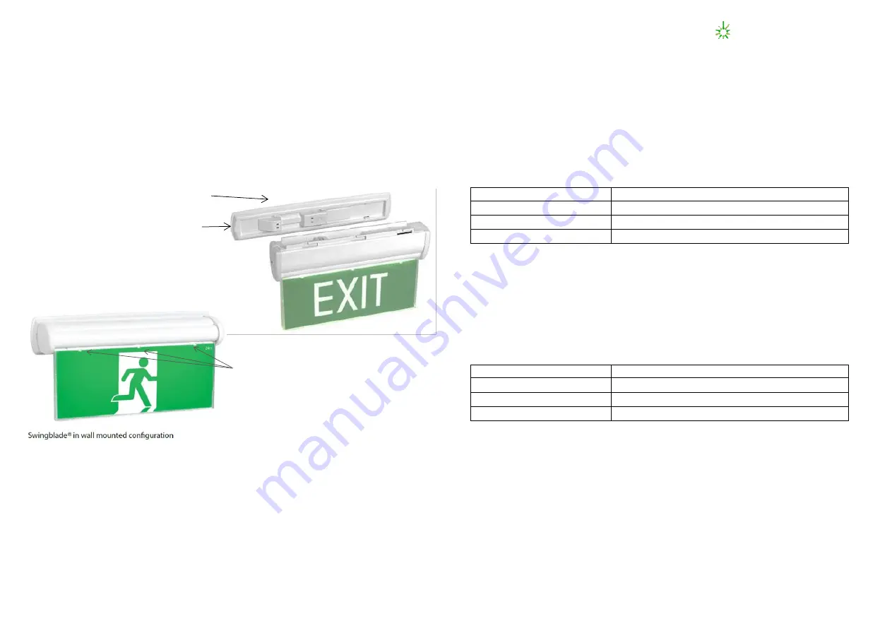
Press locking tab and slide to remove from bracket
Mounting Bracket
Locking Tab
Locking Tabs


