background image


CMS-2 CARBON MONOXIDE MONITOR 

Page 10 


© 2018 CLEMCO INDUSTRIES CORP.  

  www.clemcoindustries.com  

  Manual No. 22925, Rev. I, 04/18 
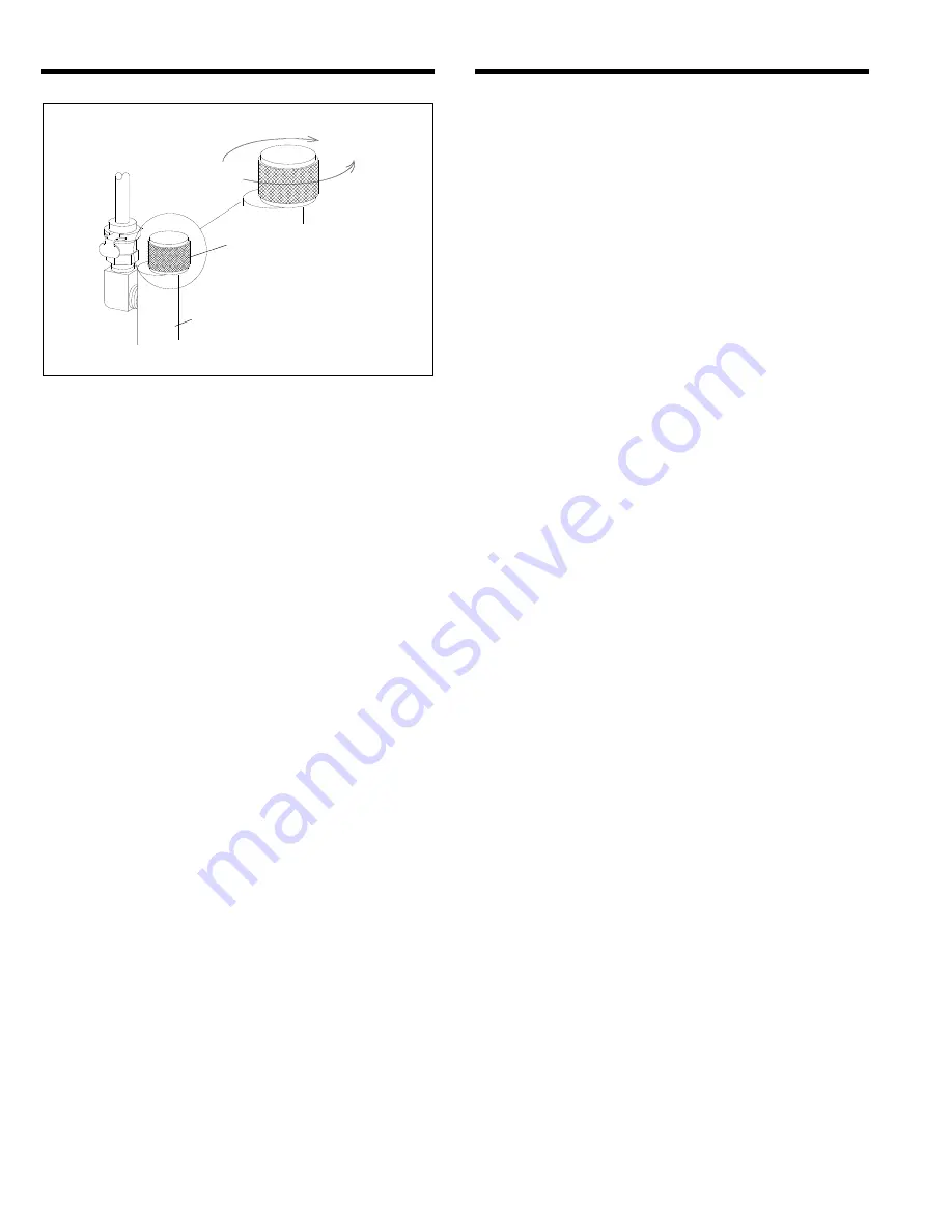


 Figure 

10 


4.6.5


Allow test gas to flow through the instrument for 

about one minute, or until the interior calibration 
indicator light turns red. 

 
4.6.6

  After the calibration light turns red, the initial 

phase of the calibration test is complete. Return the 
instrument to operating mode per Section 4.8. If the 
indicator light does not turn

 red, 

proceed with Paragraph 

4.6.7. 
 

4.6.7


If after one minute of operation with test gas the 

calibration indicator light has not turned red and the 
instrument has been in operation for 30 minutes, 
calibrate the instrument per Section 4.7. If the instrument 
has not been in operation for 30 minutes, return it to 
operating mode per Section 4.8 and operate with 
sample air flowing through for at least 30 additional 
minutes. Re-test the calibration, and if the calibration 
light does not turn red, calibrate the instrument per 
section 4.7. 


4.7 Calibration


4.7.1

  Do not calibrate the instrument unless it has 

gone through two stabilizing periods and calibration 
tests, per Sections 4.3 and 4.6, and only if the calibration 
indicator light has not turned red. 
 

4.7.2

  Connect the calibration connector and 10 ppm 

test gas per Sections 4.4 and 4.5. 
 

4.7.3

  Place the Run/Calibration toggle toward 

CALIBRATION. Slowly open the flow-control knob and 
adjust the flow so the flow ball remains between 0.5 and 
0.8 SCFH (normally a little nearer to 0.8). 
 

4.7.4


Allow test gas to flow through the instrument for 

about one minute. Insert a small screwdriver into the 
calibration adjustment port and turn the potentiometer as 
follows: 


If the potentiometer is 

blue

,

 turn 

clockwise

 until the 

calibration indicator light turns red. 

  If the potentiometer is 

white

, turn 

counterclockwise


until the calibration indicator light turns red. 


4.7.5


Once the indicator is red, turn the potentiometer 

in the opposite direction until the light turns 

green

. Then, 

slowly turn the potentiometer from 

green

 to

 red 

several 

times to find the trip point. The monitor is calibrated at 
the spot where the light turns red. Return the instrument 
to operating mode per Section 4.8. 


4.8 

Return Monitor to Operating Mode


4.8.1

  Turn the flow-control knob counterclockwise to 

close the calibration-connector valve. 
 

4.8.2


Remove the calibration tubing from the monitor 

by gripping the tube-end connector, push in lightly, turn it 
counterclockwise to unlock, and pull straight out. 
 

4.8.3

  Place the calibration toggle toward the RUN 

position. The flow meter ball should rise to 0.5 to 0.8 
SCFH. After several seconds the external alarm light 
should change from 

yellow

 to 

green

, and the interior light 

should change to 

green

. If the lights respond as 

described, proceed with Section 4.8.4 to return the 
instrument to operation. If after about one minute of 
operation the lights do not change to 

green

, do both of 

the following: 


Calibrate the instrument, per Section 4.7. 

  Test instrument function by applying impurity-free 

air, per Section 4.9. 


4.8.4


Close and latch the instrument case cover. 


4.8.5


Remove the calibration connector from the test 

gas. The test gas cylinder has a positive seal, whereas 
the calibration connector valve does not. 

NOTE: If the 

connector is not removed from the test gas cylinder, 
over time the cylinder will empty. 


4.8.6 

If the tubing needs to be removed from the 

calibration connector, press and hold the slide-release 
fitting and gently pull the tubing connector from the 
fitting. 
 

4.8.7 

Store all material in a clean, dry area. 


4.9 

Impurity-Free Air (zero contamination) Test 


4.9.1 

This test should be done whenever the 

instrument stays in an alarm condition after it is returned 
to the operating mode. This test shows whether the 
alarm condition is due to contaminated air or monitor 
malfunction. 

CLOSE 

OPEN 

Calibration Connector 

Flow-Control Knob 

Turn fully clockwise to close.

Summary of Contents for CMS-2

Page 1: ...e WARNINGS are included for the health and safety of the operator and those in the immediate vicinity Electronic files include a Preface containing the same important information as in the orange cover WARNING 2018 CLEMCO INDUSTRIES CORP One Cable Car Dr Washington MO 63090 Phone 636 239 4300 Fax 800 726 7559 Email info clemcoindustries com www clemcoindustries com ...

Page 2: ...tion that if not avoided could result in minor or moderate injury WARNING Warning indicates a hazardous situation that if not avoided could result in death or serious injury DANGER Danger indicates a hazardous situation that if not avoided will result in death or serious injury 1 3 Table of Contents SUBJECT SECTION LOCATION INTRODUCTION 1 0 Scope of Manual 1 1 Safety Alerts 1 2 Table of Contents 1...

Page 3: ...ier 1 5 Operating Principles 1 5 1 The CMS monitor samples respiratory air from a breathing air source This enables one monitor to detect CO and other toxic gases in the entire breathing air system not just for one respirator The air to the respirator does not actually pass through the monitor WARNING When the CMS is correctly installed and maintained it monitors the level of CO and other oxidizab...

Page 4: ...ion Do not use the compressed air for breathing unless the exterior light is illuminated green Yellow Light Intermittent Alarm Horn approximately every 10 seconds Sample Air Failure This alerts the user that pressure in the test chamber is either too low or too high Low pressure is usually due to loss of pressure in the sample air air line High pressure is an indication that the internal regulator...

Page 5: ...d to seal pipe fittings The monitor will respond to the gases given off by these compounds Use Teflon tape for pipe thread sealer Do not use any silicone based lubricants up stream of this instrument Silicone exposure will prematurely damage the sensor 2 3 1 To ensure accurate and rapid air monitoring the monitor must be placed as close to the compressed air source as practical Ten feet of 1 8 ID ...

Page 6: ... AC to DC field conversion Serial No 4446 and greater To convert monitors with serial numbers lower than 4446 request Manual No 22925 Revision E or earlier The AC power cord provided with the monitor may be used using black as the positive A user supplied DC 2 wire cord may be used using red as positive If a new 12 volt cord is used splice the positive through the fuse and use the spade on the out...

Page 7: ...o operate relays for external alarms and shut down devices 2 6 Changing Mode Select Dip Switch to Delay Alarm Figure 5 NOTE In areas where intermittent radio frequency transmissions cause false alarms the monitor can be set to have a 10 second alarm delay to avoid false alarm conditions The dip switch is mounted on the circuit board as shown in Figure 5 WARNING Do not change the switch positions u...

Page 8: ...Section 3 3 3 2 4 If the instrument goes into an alarm exterior light remains red with continuous audible alarm after the warm up reinitiate warm up by terminating and restarting power 3 2 5 Continued alarm condition after several warm up periods indicates that the sample air exceeds the permissible contamination level or the instrument requires calibration Refer to Section 4 0 WARNING DO NOT use ...

Page 9: ...river when calibration is required 4 3 Stabilization Period 4 3 1 The monitor must be in operation for at least 30 minutes before calibration tests DO NOT test the instrument until it has gone through the warm up period and has been in operation with sample air flowing through it see Section 3 0 for at least 30 minutes 4 4 Prepare Calibration Connector NOTE Unlike ambient air calibration test gas ...

Page 10: ...un Calibration toggle toward CALIBRATION The external alarm light will immediately turn yellow and within a few seconds the intermittent audible alarm will sound the calibration indicator remains green 4 6 3 With the flow meter vertical refer to Figure 9 and slowly open the flow control knob to introduce test gas Test gas is entering the unit when the flow meter ball rises If the ball does not ris...

Page 11: ...r light turns red 4 7 5 Once the indicator is red turn the potentiometer in the opposite direction until the light turns green Then slowly turn the potentiometer from green to red several times to find the trip point The monitor is calibrated at the spot where the light turns red Return the instrument to operating mode per Section 4 8 4 8 Return Monitor to Operating Mode 4 8 1 Turn the flow contro...

Page 12: ...death 5 0 GENERAL MAINTENANCE 5 1 Care and Handling 5 1 1 This monitor is designed for portable field use and is not adversely affected by normal handling that is required of any test and measurement instrument 5 1 2 Transport the instrument in the passenger compartment of the service vehicle NOTICE Do not subject this instrument to extreme heat or cold Placing the instrument on the dashboard of t...

Page 13: ...b as the new sensor must be installed in the same orientation While supporting the circuit board carefully pull straight up to remove the sensor 6 1 9 If the sensor comes off with the housing note the tab location and remove the sensor by pulling on a couple of the sensor pins 6 1 10 Discard the old sensor to avoid attempts to reuse 6 1 11 Handle the new sensor taking care not to distort the pins ...

Page 14: ...sengage as soon as the pressure is corrected After the pressure is correctly set close the faceplate 7 2 4 If the flow meter ball does not raise or stays very low in the meter 7 2 4 1 Check internal instrumentation lines for breaks kinks or disconnection If a line has come loose reconnecting it will re establish function and the monitor can be correctly used NOTE This type of failure could be the ...

Page 15: ... 120 volt AC 22892 12 volt DC 25072 120 volt AC monitors can be field converted to 12 volt DC Refer to Section 2 4 1 Calibration connector assembly includes tube humidifier and flow control valve with connector 22893 2 Test gas 10 ppm 22865 Impurity free 11132 3 Tubing clear for Item 1 and internal per ft specify length required 29261 4 Regulator filter M5 22920 5 Filter element replacement for It...

Reviews: