background image

1990e_Ersatzteile_en.fm, 12.06.2014

P1990BA/EN 2014-06

33

Spare parts

8

1)Order no.
2)Quantity
3) Part of hydraulic service kit K2, order no. 936210
4)Dimensions

*

Order no.

<84>

<93>

<115>

<116>

<117>

<118>

<119>

<120>

7PHH602
7PHHA602

936036

935660

7PHH60Q
7PHHA60Q

936037

935685

931789

917794

935477

935406

931793

931789

Summary of Contents for 7PHH

Page 1: ...For additional product information visit our website at http www apexpowertools eu 7PHH Pulse nutsetter without shutoff Instruction Manual P1990BA EN 2014 06...

Page 2: ...pe or form in full or parts thereof or copied to another natural or machine readable language or to a data carrier whether electronic mechanical optical or otherwise without the express permission of...

Page 3: ...4 2 Change air inlet top bottom only on 7PHHA 9 4 3 Connect the tool 9 4 4 Setting up the tool 9 4 5 Troubleshooting 11 5 Maintenance 13 5 1 Service schedule 13 5 2 Fill reserve oil 14 5 3 Complete oi...

Page 4: ...4 P1990BA EN 2014 06 P1990BA EN_2014 06_7PHHIVZ fm 12 06 2014 9 3 Performance Data 37 9 4 Ambient conditions 37 10 Service 37 11 Disposal 37...

Page 5: ...the tool Before initial operation check that the suspension bail is properly fastened to the balancer 7PHHA Before using the air inlet from above make sure that the pipe plug is correctly fitted in t...

Page 6: ...n and caught by machinery Wear a hairnet Wear close fitting clothing Do not wear jewelry Sound level in the area of the user 80 dB A danger of hearing damage Wear hearing protection 1 5 Designated use...

Page 7: ...PHH 1 This instruction manual 1 Declaration of Conformity 1 Hex wrench WAF 2 3 Product description 3 1 Operation and functional elements Item Designation 1 Reverse switch 2 Exhaust air throttle torque...

Page 8: ...Order No 937447PT 7PHH Order No 937442PT 7PHHA Parameter Data Air hose Inner diameter 3 8 9 5 mm maximum length 5 m Air inlet 1 4 NPT inner diameter 7 5 mm Parameter Data Working pressure range 400 70...

Page 9: ...specifications 4 3 Connect the tool Connect the tool to the compressed air line Maximum screwing in torque 40 Nm Reaction torque at flat end Counterhold with wrench WAF 17 Activate compressed air 620...

Page 10: ...the screwed joint If the torque difference is too large it may be necessary to change the torque setting See 4 4 2 Chang ing Torque If the setting has been changed check the torque again When carryin...

Page 11: ...e to extension and worn socket Increase the speed see 4 4 1 Set ting the torque page 10 Use a shorter or more rigid exten sion Replace the socket Insufficient oil in the pulse unit no pulse build up S...

Page 12: ...12 P1990BA EN 2014 06 1994b_1_5_en bedingt fm 12 06 2014 Before initial operation 4...

Page 13: ...activation before service disconnect the tool from the compressed air supply Maintenance interval Rundowns Measures W1 100 000 Check the suspension bail for functional safety Check the air hose for we...

Page 14: ...ut the maintenance measures marked W2 after an operating time of 200 days 5 2 Fill reserve oil If X 0 see picture 2 the reserve oil is exhausted and must be refilled to guarantee a controlled process...

Page 15: ...nternal equalization hole is opened 4 To avoid air pockets fill the filling hole full of oil 5 Position the injector so that it has a sealing effect and add reserve oil until distance X for spacer B2...

Page 16: ...cture internal equalization hole is opened 3 Use adapter to connect pulse unit to the quick disconnect coupling Close shutoff valve 4 Set the working pressure to approx 500 kPa Slowly open the shut of...

Page 17: ...the injector so that it has a sealing effect and add reserve oil until distance X for spacer B2 is achieved Maintain distance X and secure with B2 Refit set bolt and ball Remove B2 NOTE Small air bubb...

Page 18: ...18 P1990BA EN 2014 06 1994c_Wartung_en bedingt fm 12 06 2014 Maintenance 5 Empty side...

Page 19: ...1990BA EN 2014 06 19 Disassembly instructions 6 6 Disassembly instructions Please refer to 8 Spare parts page 25 and 8 5 Equipment order list page 34 6 1 Remove motor unit 1 2 Changing blades Changing...

Page 20: ...ring force 3 CAUTION Skin irritation in case of direct contact with oil Wear protective gloves CAUTION Hydraulic blade is under spring pressure Wear protective goggles NOTE Permitted only if filling i...

Page 21: ...motor unit CAUTION Only perform installation in accordance with exploded drawing see 8 3 Motor unit page 30 Incorrect installation can lead to uncontrolled reactions e g unexpected start up or parts b...

Page 22: ...ions 7 7 1 1 Install rotor cover 1 Press 59 in with C4 see X 2 Examine Y with thickness gage If dimension Y step 1 with support C5 C6 C7 repeat Press 61 in with C8 C8 59 C4 C5 C6 C7 X 54 55 X Base 0 0...

Page 23: ...ons 7 7 2 Install pulse unit 7 2 1 Assembling the hydraulic blades NOTE To prevent damage lubricate the gaskets and O rings using grease order no 914392 before assembly 1 2 3 4 5 6 7 8 F1 93 F1 98 93...

Page 24: ...24 P1990BA EN 2014 06 1994d_Reparatur_en bedingt fm 12 06 2014 Assembly instructions 7...

Page 25: ...nce and increased maintenance requirements If non original spare parts are installed the tool manufacturer is entitled to declare all warranty obligations for null and void We would be glad to prepare...

Page 26: ...26 P1990BA EN 2014 06 1990e_Ersatzteile_en fm 12 06 2014 Spare parts 8 8 1 Pistol grip 7PHH Adhesive order no 914860 Grease order no 914392...

Page 27: ...1990e_Ersatzteile_en fm 12 06 2014 P1990BA EN 2014 06 27 Spare parts 8 1 Order no 2 Quantity 3 Part of motor service kit K1 order no 936158 4 Dimensions...

Page 28: ...28 P1990BA EN 2014 06 1990e_Ersatzteile_en fm 12 06 2014 Spare parts 8 8 2 Pistol grip 7PHHA Adhesive order no 914860PT Grease order no 914392...

Page 29: ...1990e_Ersatzteile_en fm 12 06 2014 P1990BA EN 2014 06 29 Spare parts 8 1 Order no 2 Quantity 3 Part of motor service kit K1 order no 936158 4 Dimensions...

Page 30: ...30 P1990BA EN 2014 06 1990e_Ersatzteile_en fm 12 06 2014 Spare parts 8 8 3 Motor unit Axial clearance see 7 1 1 Install rotor cover page 22...

Page 31: ...1990e_Ersatzteile_en fm 12 06 2014 P1990BA EN 2014 06 31 Spare parts 8 1 Order no 2 Quantity 3 Part of motor service kit K1 order no 936158 4 Dimensions...

Page 32: ...1990e_Ersatzteile_en fm 12 06 2014 Spare parts 8 8 4 Pulse unit Tightening torque see 7 2 Install pulse unit page 23 For disassembly note the position of the balls in the control disc Reassemble balls...

Page 33: ...06 33 Spare parts 8 1 Order no 2 Quantity 3 Part of hydraulic service kit K2 order no 936210 4 Dimensions Order no 84 93 115 116 117 118 119 120 7PHH602 7PHHA602 936036 935660 7PHH60Q 7PHHA60Q 936037...

Page 34: ...34 P1990BA EN 2014 06 1990e_Ersatzteile_en fm 12 06 2014 Spare parts 8 8 5 Equipment order list 1 Order no...

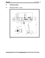
Page 35: ...1990f_TechnDaten_en fm 12 06 2014 P1990BA EN 2014 06 35 Technical data 9 9 Technical data 9 1 Dimensions 7PHH in mm Abb 9 1...

Page 36: ...36 P1990BA EN 2014 06 1990f_TechnDaten_en fm 12 06 2014 Technical data 9 9 2 Dimensions 7PHHA in mm Abb 9 2...

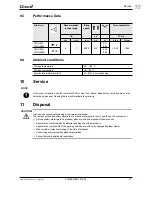
Page 37: ...PHHA60Q 1 4 0 79 0 84 Storage temperature 25 60 C Working temperature 5 40 C Permissible relative humidity 25 90 non condensing CAUTION Injuries and environmental damage from improper disposal The com...

Page 38: ...38 P1990BA EN 2014 06 1990f_TechnDaten_en fm 12 06 2014 Disposal 11...

Reviews: