CleaverBrooks 4WI Operation, Service And Parts Manual Download Page 98

Adjustment Procedures

6-12

750-211 (revised 2009)

Promethean Boilers, Model 4WI Manual

The program relay used may be of the type that provides message infor-
mation that includes a constant flame signal of DC voltage. In this case 
a separate DC voltmeter is not required.

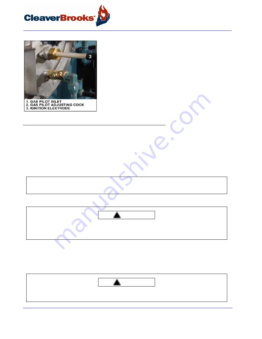
To measure and adjust the pilot:

1.

 When making a pilot adjustment, turn the manual-automatic switch to 

“manual” and the program control to “close.” Open both the pilot cut-
off cock and the pilot adjusting cock. The main gas cock should remain 
closed.
The regulator in the pilot line, if provided, is to reduce the gas pressure 
to suit the pilot’s requirement of between 5” to 10” WC. Regulator 
adjustment is not critical, however, with a lower pressure the final 
adjustment of the pilot flame with the adjusting cock is less sensitive.

FIGURE 6-12.

Gas Pilot Adjusting Cock and Electrode

2.

Connect the micro-ammeter.

3.

Turn the burner switch “on.” Let the burner go through the normal pre-purge cycle. When the ignition trial 
period is signaled, set the program switch to the “Test” position to stop the sequence.

4.

If the pilot flame is not established within 10 seconds, turn off the burner switch. Repeat the lighting attempt.

5.

When the pilot flame is established, and with the pilot adjusting cock wide open, remove the flame detector 
from the burner plate. The pilot flame can then be observed through this opening. 

6.

To make the final adjustment, slowly close the gas pilot adjusting cock until the flame can no longer be seen 
through the sight tube. Then slowly open the cock until a flame providing full sight tube coverage is observed.

The adjustment must be accomplished within the time limit of the safety switch or approximately 30 seconds 
after the detector is removed. If the control shuts down, manually reset it. Replace the detector and repeat the 
process from step 5.

NOTE:

 On an initial starting attempt, portions of the fuel lines may be empty and require “bleeding” time. It is better 

to accomplish this with repeated short lighting trial periods with intervening purge periods than to risk prolonged fuel 
introduction. If the pilot does not light after several attempts, check all components of the pilot system.

Wear a protective shield or suitable glasses and keep eyes sufficiently away from the sight tube opening. Never remove 
the flame detector while the main burner is firing. Failure to follow these instructions could result in serious injury or 
death. 

When checking the pilot flame, be aware the electrode is energized. Failure to follow these instructions could result in 
serious injury or death.

!

Warning

!

Warning

Summary of Contents for 4WI

Page 1: ...Model 4WI Operation Service and Parts Manual 750 211 12 09 Promethean Boilers 100 to 800 HP Steam and Hot Water Fuel Light Oil Gas or Combination...

Page 2: ...ified on the boiler name plate DANGER WARNING Should overheating occur or the gas sup ply valve fail to shut off do not turn off or disconnect the electrical supply to the boiler Instead turn off the...

Page 3: ...nts to UL 795 Commercial In dustrial Gas Heating Equipment and or the National Fuel Gas Code ANSI Z223 1 DANGER WARNING The boiler and its individual shutoff valve must be disconnected from the gas su...

Page 4: ...r other applicable codes there are a variety of electric controls and safety devices which vary consider ably from one boiler to another This manual contains information designed to show how a basic b...

Page 5: ...CLEAVER BROOKS Model 4WI Promethean Boilers Operation and Maintenance Manual Manual Number 750 211 Release Date December 2009...

Page 6: ...t of this document may be reproduced stored in a retrieval system or transmitted in any form or by any means without the prior writ ten consent of Cleaver Brooks Cleaver Brooks 11950 West Lake Park Dr...

Page 7: ...5 1 4 3 Water Column 1 6 1 4 4 Steam Pressure Gauge and ALWCO 1 6 1 4 5 Safety Valve s 1 6 1 5 Hot Water Controls All Fuels 1 7 1 5 1 Pressure and Temperature Gauges 1 7 1 5 2 Controls 1 7 1 5 3 Low W...

Page 8: ...ow 2 19 2 15 Modulating Firing 2 20 CHAPTER 3 Waterside Care and Requirements 3 1 3 1 Overview 3 1 3 2 Water Requirements 3 2 3 2 1 Hot Water Boilers 3 2 3 2 1 1 Air Removal 3 2 3 2 1 2 Minimum Water...

Page 9: ...Blowdown Controlling TDS 3 12 3 7 2 Frequency of Manual Blowdown 3 12 3 7 3 Manual Blowdown Procedure 3 13 3 8 Periodic Inspection 3 13 3 9 Preparation for Extended Layup 3 14 CHAPTER 4 Sequence of O...

Page 10: ...hutdown All Fuels 5 12 5 9 1 Operating 5 15 5 9 2 Shutdown 5 15 5 10 Control Operational Test and Checks 5 16 CHAPTER 6 Adjustment Procedures 6 1 6 1 Overview 6 1 6 2 Linkage Modulating Motor and Air...

Page 11: ...ustment 6 18 6 17 1 Burner Low Fire Adjustment 6 20 6 18 Low Gas Pressure Switch 6 21 6 19 High Gas Pressure Switch 6 21 6 20 Fuel Oil Pressure and Temperature General 6 21 6 21 Fuel Oil Combustion Ad...

Page 12: ...auge Glass 8 5 8 5 Electrical Controls 8 6 8 6 Flame Safety Control 8 8 8 6 1 Checking Pilot Flame Failure 8 9 8 6 2 Checking Failure to Light Main Flame 8 10 8 6 3 Checking Loss of Flame 8 10 8 7 Oil...

Page 13: ...ling Coil 8 25 8 17 7 Flexible Coupling Alignment 8 25 8 17 8 Air Compressor Replacement 8 26 8 17 8 1 Dismantling 8 26 8 17 8 2 Reassembly 8 27 8 18 Refractory 8 27 8 18 1 Furnace Liner 8 28 8 18 2 T...

Page 14: ...5 Burner Drawer Gas Pilot Models 100 200 350 400 HP 9 30 9 2 24 96 106 Burner Drawer Gas Pilot Models 101 200 500 800 HP 9 32 9 2 25 Burner Housing Support 60 9 34 9 2 26 Burner Housing Support 67 106...

Page 15: ...e various firetube passages The flame orig inates in the furnace As the combustion gases travel down the furnace and through the various firetube channels heat from the flame and combustion gases is t...

Page 16: ...bustion air stream thereby improving combustion The Promethean Firetube Boiler line is designed to incorporate Induced Flue Gas Recir culation IFGR when firing either natural gas and or light oil and...

Page 17: ...authorities having jurisdiction are to be consulted permits obtained etc All Promethean boilers in the series comply when equipped with optional equipment to Industrial Risk Insurers IRI Factory Mutu...

Page 18: ...setting of the pressure relieving valve s to prevent frequent valve opening during normal operation The type of service that your boiler is required to provide has an important bearing on the amount...

Page 19: ...off The style of Low Water Cutoff is determined by the design pressure of the vessel or by cus tomer preference The Level Master for operation and maintenance information consult the Level Master manu...

Page 20: ...r drops below the master low water cutoff point Manual reset type requires manual resetting in order to start the burner after a low water condition FIGURE 1 8 Steam Pressure Gauge and ALWCO Hot Water...

Page 21: ...t on auto matic 2 High Limit Temperature Control Breaks a circuit to stop burner operation on a rise of temperature at a selected setting It is adjusted to stop the burner at a preselected temperature...

Page 22: ...to the entrance of the combustion air fan The IFGR damper controls the volume of flue gas induced into the combustion air stream The damper is located in the flue gas transfer port and is positioned...

Page 23: ...l boilers with two jackshaft drive arms as defined above a proximity switch is used to prove that the correct linkage connection is made Refer to the wiring diagram provided with the boiler FIGURE 1 1...

Page 24: ...rs from the rear of the air inlet shrouds which reduces the sound level and captures heat from the boiler and stack flue out let 7 Front Door Insulation If NOx emissions are below 60 ppm the front doo...

Page 25: ...um firing posi tion for ignition High pressure boilers above 15 psi can be wired for both low pressure and high pressure modulation which enables the boiler to oper ate at lower pressure during off lo...

Page 26: ...of fuel through a linkage system connected to the gas but terfly valve and or oil through a cam operated metering valve Fuel input and air are thus properly proportioned for most effi cient combustio...

Page 27: ...ual controls furnished with any given boiler will depend upon the type of fuel for which it is equipped and whether it is a hot water or steam boiler Refer to the applicable group or groups within Cha...

Page 28: ...permits the positioning of the modulating motor to a desired burner firing rate when the manual automatic switch is set on manual It is used primarily for initial or subsequent setting of fuel input t...

Page 29: ...art prevents burner operation in the event anything causes the flame relay to hold in during this period 18 Indicator Lights Provide visual information of boiler operation as follows indicator lights...

Page 30: ...ed a normally open vent valve optional equipment is installed between them Its purpose is to vent gas to the atmosphere should any be present in the pilot line when the pilot valves are closed The val...

Page 31: ...that is closed whenever main gas line pressure is below a preselected pressure Should the pressure rise above the setting the switch contacts will open a circuit causing the main gas valve s to close...

Page 32: ...in the programmer and allows fuel oil to flow from the oil metering valve to the burner nozzle A light oil fired burner uses two valves operating simultaneously 5 Fuel Oil Controller An assembly combi...

Page 33: ...ilot is furnished a solenoid valve is provided to control flow of fuel to the pilot nozzle It is energized through programmer contacts It is de ener gized to shut off pilot fuel flow after the main fl...

Page 34: ...l C Air Filter The filter cleans the air supply prior to entering the air pump D Check Valve Prevents lubricating oil and compressed air from surging back through the pump and air filter when the pump...

Page 35: ...heater must be turned off during extended boiler lay up or at any time the fuel oil transfer pump is stopped 2 Oil Heater Thermostat Steam Senses fuel oil temperature and controls the opening and clo...

Page 36: ...er firing if fuel oil temperature is lower than required for oil burner operation 15 Oil Supply Pressure Gauge Indicates fuel oil pressure in the oil heater and supply pressure to the fuel oil con tro...

Page 37: ...l light off Its disc has an orifice to permit a continuous circulation of hot fuel oil through the controller I Air Purge Valve Solenoid valve opens simultaneously with closing of oil solenoid valve a...

Page 38: ...Speed Drive VSD optional works in conjunction with the air damper actuator When high fire is not required the VSD reduces amperage to the fan motor reducing energy consumption and the corre sponding...

Page 39: ...provided from the line that supplies oil under pressure for the main flame A solenoid actuated valve controls flow of oil to the pilot nozzle The valve is energized simultaneously with the ignition tr...

Page 40: ...ol 2 16 750 211 revised 2009 Promethean Boilers Model 4WI Manual 2 12 Oil Fuel Flow Light Oil In Figure 2 16 the oil flow is indicated by arrows and the pertinent controls are identified FIGURE 2 16 D...

Page 41: ...the air damper are controlled simultaneously at all times by the modulating motor to proportion combustion air and fuel for changes in load demand 2 13 Oil Fuel Flow Heavy Oil In Figure 2 17 the heav...

Page 42: ...an Boilers Model 4WI Manual are satisfied respectively by sufficient combustion air pressure from the forced draft fan pressurized air from the air pump and sufficient oil temperature and pressure FIG...

Page 43: ...x orifice type burner FIGURE 2 18 Gas Train The main gas valve is of the normally closed type and is opened energized in proper sequence by the program ming relay The butterfly gas valve modulates the...

Page 44: ...ing control The modulating motor commonly called a damper motor is reversible It has an internal limit switch that restricts shaft rotation to 90 During normal operation the motor will move in either...

Page 45: ...ring this time neither the manual flame control nor the modulating control have any control over the damper motor regardless of their setting An optionally equipped boiler uses a second integral switc...

Page 46: ...Burner Operation and Control 2 22 750 211 revised 2009 Promethean Boilers Model 4WI Manual...

Page 47: ...dance with prevailing codes and practices Water requirements for both steam and hot water boilers are essential to boiler life and length of service It is vital care be taken in placing the pressure v...

Page 48: ...where water vapor condenses which can cause corrosion in the boiler and stack Condensation is more severe on a unit that operates intermittently and which is greatly oversized for the actual load Cond...

Page 49: ...Constant circulation through the boiler mitigates the possibility of stratification within the boiler and results in more even water temperatures to the system A rule of thumb of 3 4 to 1 gpm per boil...

Page 50: ...h the boilers Proportional flow can best be accomplished by use of balancing valves and gauges in the supply line from each boiler If balancing valves or orifice plates are used a significant pressure...

Page 51: ...s nitrogen Caution must be exercised to ensure that the proper relationship of pressure to temperature exists within the boiler so that all of the boiler s internal surfaces are fully wetted at all ti...

Page 52: ...or less It is only necessary to open the water supply line valve and the water feeder discharge valve 3 3 Water Treatment Properly treated boiler feed water coupled with good engineering and operating...

Page 53: ...ly determine the amount of raw water admitted to the boiler steam or hot water and to aid in maintaining proper waterside condi tions 3 4 Cleaning 3 4 1 Hot Water and Steam Piping Steam and water pipi...

Page 54: ...the scheduling or frequency of blowdown may need to be revised The need for periodic draining or wash out will also be indicated Any oil or grease present on the heating surfaces should be removed pr...

Page 55: ...he grease the solution may carry will contaminate the valves Use care in removing and reinstalling the valves Refer to Chapter 8 Section 8 17 for valve installation instructions 5 An overflow pipe sho...

Page 56: ...system and boiler that has been initially cleaned filled with raw water and water treated with no make up water added will require no further cleaning or treatment However since the system new or old...

Page 57: ...eatment are required to prevent the solids from forming harmful scale and sludge Scale has a low heat transfer value and acts as an insulation barrier Scale retards heat transfer which not only result...

Page 58: ...rescribed amount of dissolved solids When surface or continuous blowdown is not utilized manual blowdown is used to control the dissolved or sus pended solids in addition to the sludge This will invol...

Page 59: ...ler Slightly crack the downstream valve and then close it tightly Under no circumstances should a blowoff valve be left open and the operator should never leave until the blow down operation is comple...

Page 60: ...ndholes manhole and front or rear doors Adequately vent the pressure vessel prior to entry Clean out the low water cutoff piping the water level controls and cross connecting pipes Replace the water g...

Page 61: ...ratures may exist In the dry storage method the boiler must be thoroughly dried because any mois ture would cause corrosion Both fireside and waterside surfaces must be cleaned of all scale deposits s...

Page 62: ...Waterside Care and Requirements 3 16 750 211 revised 2009 Promethean Boilers Model 4WI Manual...

Page 63: ...The operating limit pressure control steam boiler or the operating limit temperature control hot water boiler and high limit pressure or temperature control switches are closed All other limit circui...

Page 64: ...Operating limit control OLC pressure or temperature High limit control HLC pressure or temperature Low water cutoff LWCO Gas oil selector switch GOS combination burner only Oil drawer switch ODS oil b...

Page 65: ...e same time the program relay signals the modulating damper motor MDM to open the air damper The damper begins to open and drives to its full open or high fire position Opening the damper motor allows...

Page 66: ...d of the proving period if the flame detector still detects main flame the ignition transformer and pilot valve are de energized and pilot flame is extinguished 4 3 3 Run Cycle With main flame establi...

Page 67: ...contacts of the air purge relay APR to provide an air purge of the oil nozzle The damper motor returns to the low fire posi tion if it is not already in that position The blower motor start circuit i...

Page 68: ...re operation can be resumed 4 Loss of Flame If a flame outage occurs during normal operation and or the flame is no longer sensed by the detector the flame relay will trip within 2 to 4 seconds to de...

Page 69: ...it shuts down or refuses to operate Never attempt to circumvent any of the safety features Preventive maintenance and scheduled inspection of all components should be followed Periodic checking of th...

Page 70: ...Sequence of Operation 4 8 750 211 revised 2009 Promethean Boilers Model 4WI Manual...

Page 71: ...breakers dropped out overloads etc Check reset of all starters and controls having manual reset features Check the lockout switch on the programmer and reset if necessary The boiler should be filled...

Page 72: ...5 1 Air Compressor Motor Rotation Before operating the boiler feed pump or oil supply pump be sure all valves in the line are open or properly posi tioned For safety reasons perform a final pre startu...

Page 73: ...g motor returns to low fire position before the operat ing limit control opens It is further desirable to have the modulating control s low point setting somewhat below the cut in setting of the opera...

Page 74: ...ions provided in Chapter 6 On initial starting attempts several efforts might be required to fully bleed the pilot line While checking pilot adjustment observe whether the pilot flame is extinguished...

Page 75: ...the run position 5 5 Firing Preparations for No 2 Oil Series 100 200 Prior to initial firing oil flow and pressure should be established and verified Atomizing air pressure should also be established...

Page 76: ...otor starter Momentarily energize the starter to check for proper pump rotation With the rotation verified operate the pump to determine that oil circulation exists Observe the oil burner pressure gau...

Page 77: ...p is running final adjustment can be made at the fuel oil controller Final regulation of oil flow to the nozzle can be done later if necessary by adjusting the metering cam screws as outlined in Chapt...

Page 78: ...venting oil flow must be determined and corrected to avoid damage to the pump s internal mechanism A vacuum gauge should be installed in the oil suction line and its reading observed and recorded for...

Page 79: ...mperature of 220 230 F The electric heater will be turned off as soon as steam or hot water provides heat Close the manual bypass valve after the temperature rise on the fuel oil controller thermomete...

Page 80: ...ly available consult the Cleaver Brooks Service Department and be ready to provide the boiler serial number Chapter 6 contains additional information along with standard gas flow and pressure requirem...

Page 81: ...s should not be changed unless conditions includ ing boiler settings change In that case it will be necessary to contact your local Cleaver Brooks authorized repre sentative for assistance After the I...

Page 82: ...removal and installation 5 9 Startup Operating and Shutdown All Fuels Depending upon the fuel being burned the applicable pervious sections in this chapter should be reviewed for pre liminary instruc...

Page 83: ...50 211 revised 2009 Promethean Boilers Model 4WI Manual 5 13 5 9 Startup Operating and Shutdown All Fuels FIGURE 5 14 Overtravel Linkage Settings FIGURE 5 15 Flange Collar and Damper Settings Top View...

Page 84: ...third cam screw Operate at the increased fuel input rate for a period of time until an increase is noted in pressure or temperature After the boiler is thoroughly warmed turn the manual flame control...

Page 85: ...he load demand light no longer glows Shutdown through flame failure will actuate the flame failure light and alarm if so equipped and the load demand light will remain lit The cause of this type of sh...

Page 86: ...erating limit control Observe the thermometer to verify the desired settings at the point of cutout and again when the burner restarts Return the manual automatic switch to automatic and check the mod...

Page 87: ...apply to standard components furnished on steam or hot water boilers fired with gas and or the various grades of oil In order to reduce stress on boiler components and to improve boiler operating eff...

Page 88: ...ide proper fuel air ratios through the firing range In linkage adjustments there are several important factors that must serve as guides 1 The modulating motor must be able to complete its full travel...

Page 89: ...counterclockwise to the stopscrew opens the damper Normally the rate of flow of air through the damper with the rotor in low fire position is about one third of maximum for a standard burner or one si...

Page 90: ...switches are actuated by adjustable cams attached to the motor shaft Factory replacement motors have the cams preset The low fire start switch is set to make the red and yellow leads at approximately...

Page 91: ...rs the modulat ing control must be set to ensure the burner is at its minimum low fire position before the operating limit control either starts or stops the burner When adjusting or setting controls...

Page 92: ...ressure or temperature drops back to B the oper ating limit control closes and the burner will restart The modulating control will signal the modulating motor to be in a low fire position If the load...

Page 93: ...new construction conditions the boiler is initially started and set to operate under less than full load requirements As soon as possi ble thereafter the controls should be reset to provide maximum ut...

Page 94: ...ure Control Steam Turn the adjusting screw until the indicator is opposite the low point of the desired modulating range Modulated firing will range between the low point and a higher point equal to t...

Page 95: ...ithin which modulating action is desired With the cover off turn the adjustment wheel until the pointer indicates the desired range FIGURE 6 8 Hot Water Controls 6 10 High Limit Temperature Control Ho...

Page 96: ...ini mum pressure but not too close to that point to cause nuisance shutdowns The run test switch on the program relay should be set to Test Turn the burner switch on The blower will start provided tha...

Page 97: ...n be restarted Turn the adjusting screw up a half turn or so to remake the circuit After making the adjustment recycle the control to be sure that normal operation is obtained The Test switch must be...

Page 98: ...lot flame is established and with the pilot adjusting cock wide open remove the flame detector from the burner plate The pilot flame can then be observed through this opening 6 To make the final adjus...

Page 99: ...variables in both the properties of gas and the supply system it will be necessary to regulate the pres sure of the gas to a level that produces a steady dependable flame that yields the highest comb...

Page 100: ...3 23 300 3 32 5 350 3 48 5 400 3 60 500 4 43 600 4 56 700 4 62 800 4 83 TABLE 6 2 Pressure Altitude Correction Factors Altitude Feet Above Sea Level Correction Factor 1000 1 04 2000 1 07 2500 1 09 300...

Page 101: ...ally measure gas in cubic feet at line or supply pressure The pressure at which each cubic foot is measured and the correction factor for the pressure must be known in order to convert the quantity in...

Page 102: ...pressure and flow requirements can be determined as follows Pressure Correction for the 2 000 feet altitude must be made since altitude has a bearing on the net regulated gas pressure The standard gas...

Page 103: ...which gas flow can be determined After a short observation period the information aids in adjusting the regulator to increase or decrease flow as required to obtain the rating Final adjustment of the...

Page 104: ...fuel burned This can be accomplished under laboratory conditions however it s not practical to attempt to meet this condition in a boiler Stoichiometric combustion however is the reference point used...

Page 105: ...ge subject to local regulations The percent O2 recorded on an instrument equates to percent excess air i e 3 O2 is approximately 15 excess air and 4 O2 is approximately 20 excess air The exact percent...

Page 106: ...air is ordinarily fixed at any given point in the modulating cycle the flue gas reading is determined by varying the input of gas fuel at that setting The adjustment is made to the metering cam by me...

Page 107: ...er a pressure drop Press the reset lever after pressure is restored Be sure that the mercury switch equipped control is level FIGURE 6 16 Gas Train Pressure Switches 6 19 High Gas Pressure Switch Adju...

Page 108: ...pplier will be able to give you more exact information based on an analysis of the oil FIGURE 6 17 Oil Viscosity Chart Review of the applicable maintenance instructions given in Chapter 8 will aid in...

Page 109: ...ntroller to increase or decrease oil pressure Adjustments to the pressure should be done before attempting to adjust the screws in the metering cam Ideally the cam profile spring should be as close to...

Page 110: ...olding screws are properly tightened The diffuser location on gas fired boilers is important There should be 1 4 distance between the edges of the diffuser fins and gas outlet tubes spuds coming from...

Page 111: ...htly in the body with the swirler and the seating spring in place See Chapter 8 Section 8 7 for additional nozzle tip information Check to see that the flame detector sight tube and the gas pilot tube...

Page 112: ...at approximately 40 F below the maximum operating temperature of the heater 6 25 High Oil Temperature Switch Optional The HOTS prevents the burner from starting or stops its operation if the temperatu...

Page 113: ...red for proper flow 6 29 Hot Water Oil Heater Thermostat 400 and 600 Series To adjust the thermostat insert a screwdriver into the center slot in the control cover and turn the dial until the pointer...

Page 114: ...Adjustment Procedures 6 28 750 211 revised 2009 Promethean Boilers Model 4WI Manual...

Page 115: ...sted remedies Familiarity with the programmer and other controls in the system may be obtained by studying the contents of this manual Knowledge of the system and its controls will make troubleshootin...

Page 116: ...ety switch requires resetting 3 Limit circuit not completed no voltage at end of limit circuit program relay terminal A Pressure or temperature is above setting of operation control Load demand light...

Page 117: ...bustion or atomizing air proving switches defective or not properly set B Motor starter interlock contact not closed 5 Flame detector defective sight tube obstructed or lens dirty PILOT FLAME BUT NO M...

Page 118: ...inadequate flame signal or open control in the running interlock circuit 7 Improper air fuel ratio lean fire A Slipping linkage B Damper stuck open C Fluctuating fuel supply 1 Temporary obstruction in...

Page 119: ...r room should be kept free of all material and equipment not necessary to the operation of the boiler or heating system Even though the boiler has electrical and mechanical devices that make it automa...

Page 120: ...during this time Any major repairs or replacements that may be required should also if possible be coordinated with the period of boiler shutdown TABLE 8 1 Recommended Boiler Inspection Schedule Dail...

Page 121: ...er deposits can be very moisture absor bent and may attract moisture to form corrosive acids that will dete riorate fireside metal Clean out should be performed at regular and frequent intervals depen...

Page 122: ...for blowdown instructions and internal inspection procedures Since low water cutoff devices are generally set by the original manufacturer no attempt should be made to adjust these controls to alter...

Page 123: ...p and additional feed water treatment that might not otherwise be necessary Since the boiler and system arrangement usually make it impractical to perform daily and monthly maintenance of the low wate...

Page 124: ...age the mechanism Be certain that controls are correctly leveled The internal piping leading to the pressure control actu ators should be cleaned if necessary Covers should be left on controls at all...

Page 125: ...the motor current is normal replace them with new overloads If the condition continues after replace ment it will be necessary to determine the cause of excessive current draw at the overloads Power s...

Page 126: ...4 FRN 10 FRN 12 FRN 17 1 2 FRN 45 FRN 30 FRN 25 FRN 15 FRN 10 FRN 7 FRN 450 FRN 350 FRN 250 FRN 200 FRN 175 FRN 150 FRN 100 FRN 90 FRN 70 FRN 60 FRN 40 FRN 30 FRN 20 FRN 12 FRN 9 FRN 7 FRN 5 FRN 4 1 2...

Page 127: ...and upon loss of flame Each of the conditions should be checked on a scheduled basis The following tests should be used to test the complete safeguard system If the sequence of events is not as descri...

Page 128: ...ds after the main burner ignition trial ends The control will lock out on a safety shutdown The flame failure light and optional alarm will be activated The blower motor will run through the post purg...

Page 129: ...r gasket If necessary tap the strainer cover gently to loosen Check the cover gasket for damage and replace if necessary Slip pliers into the cross on the top of the strainer and twist counter clockwi...

Page 130: ...osion which may make the nozzle unfit for further use Take the necessary precautions in working with solvents The tip and swirler are a matched set which are precision lapped at the time of assembly T...

Page 131: ...present If there are cracks replace the electrode since they can cause grounding of the ignition voltage Since carbon is an electrical conductor it is necessary to keep the insu lating portion of elec...

Page 132: ...diffuser If the burner is a high turndown burner HTB model check to see that the diffuser is properly located in reference to the gas spuds There should be 1 4 between the edge of the diffuser fins an...

Page 133: ...ecked replace the entire operator portion 8 10 Solenoid Valves Foreign matter between the valve seat and seat disc can cause leakage Valves are readily disassembled however care must be used during di...

Page 134: ...nding determine the cause of the binding and correct as necessary Linkage rod end attachment points should be marked on the vari able displacement linkage arms as an aid in subsequent reassembly FIGUR...

Page 135: ...chains so the lifting point is over the motor shaft centerline and the center of balance for the fan motor cassette This point is approximately 4 inches from the motor backplate for 600 800 HP units...

Page 136: ...on the load type of fuel and combustion tempera tures FIGURE 8 22 Induced Flue Gas Recirculation IFGR Air Flow 1 With the IFGR damper exposed inspect the internal linkages for secure connections and...

Page 137: ...nspect the airbox gasket for damage 8 14 Fan Motor Cassette Installation FIGURE 8 23 Fan Motor Cassette Open To close the fan motor cassette 1 Check that all adjustment screws are tight and check the...

Page 138: ...the lifting lever or by raising the steam pressure should be based on the recommendation of your boiler inspector and or the valve manufacturer and in accor dance with Sections VI and VII of the ASME...

Page 139: ...and spring Do not drop or mishandle Check for nicks or scratches Check that the pin holding the metering portion is not protruding 6 Back off the packing gland 7 Remove the capscrews holding the jack...

Page 140: ...d replace the cam Mate the match marks and secure the setscrews Be sure the cam spring is centered in the roller 18 Restor oil flow Test fire the burner at various firing rates being certain that the...

Page 141: ...ittle maintenance However the life of the pump is dependent upon a sufficient supply of clean cool lubricating oil The oil level in the air oil tank must be observed closely Lack of oil will damage th...

Page 142: ...basis while the other is serviced 8 17 4 Air Oil Tank Pads of steel wool are used in the air to oil tank as a filtering medium to separate the lube oil form the compressed air The pads play a very im...

Page 143: ...f misalignment The check should be done on the top of the coupling and at 90 degrees A useful aid is to hold a flashlight behind the straightedge so that any gap can readily be seen Shim stock of appr...

Page 144: ...and lift tubing A high enough to prevent drainage of lubricating oil from the tank FIGURE 8 31 Air Pump Components 3 Disconnect the flared nut at the orifice fitting 4 Remove the two sheet metal screw...

Page 145: ...y first then tighten the setscrew against the shaft Clean or remove any dust or grime from the blades prior to re installing When replacing the retainer screen a slight force may be required to push t...

Page 146: ...refer to Chapter 9 to order proper replacement items Remove existing refractory Thoroughly clean the furnace to remove all old refractory cement or other foreign material to ensure the new liner seat...

Page 147: ...rate for sev eral hours to thoroughly dry the refractory For detailed information request Bulletin C10 5921 from your local Cleaver Brooks representative 8 18 3 Installation The following procedure i...

Page 148: ...measures less than 1 2 full width cut two pieces see note 1 on Figure 8 33 5 Install bricking tool as shown on DETAIL A and continue installing upper half by alternating one arch brick and one corres...

Page 149: ...rature they should be expected to show minor cracks due to contraction expansion recessing themselves when the refractory cools Cracks up to approximately 1 8 across may be expected to close at high t...

Page 150: ...n all retaining bolts in until snug Tighten the bolts uniformly starting at the top center and alternating between the top and bottom bolts until both are tight Do not over tighten Tighten alternate b...

Page 151: ...the drain plug run the motor for 10 to 20 minutes to expel any excess grease The filler and drain plugs should be thoroughly cleaned before they are replaced The lubricant used should be clean and eq...

Page 152: ...element from the shell and scrap ing any accumulation of carbonized oil or sludge deposits that may have collected on the heat exchanging surfaces Before breaking any of the electrical connections to...

Page 153: ...nt antifreeze and water is generally used as the heat transfer solution If there is no danger of freezing plain water may be used as a replenishment if necessary to refill Evidence of oil in either th...

Page 154: ...Readjustment of the burner may be required due to variations in fuel composition A combustion analyzer should be used to adjust air fuel ratio for maximum operating efficiency If your burner requires...

Page 155: ...ish complete information when ordering parts by giving the item number description and the quantity of parts desired together with the complete nameplate data including all electrical requirements Rep...

Page 156: ...30 60 LH 132 02337 RH LH RH 132 02427 132 02426 60 RH LH RH LH 132 02430 132 02431 132 02417 132 02418 30 60 67 132 02411 132 02410 132 02308 132 02307 132 02390 132 02391 132 02403 132 02404 85 78 6...

Page 157: ...N BLANKET 930 00135 8 797 01813 904 00012 872 00362 872 00443 828 00039 4 6 7 5 3 GASKET TAPE 15 12 59 5 59 5 65 872 00500 PIN WELDING 903 00297 65 2 1 QTY SQ FT OZ OZ 90 15 SQ FT 21 SQ FT 70 12 OZ 95...

Page 158: ...442 457 03441 WITHOUT COMBUSTION DOOR WITH COMBUSTION DOOR 67 457 03449 457 03450 WITHOUT COMBUSTION DOOR WITH COMBUSTION DOOR 78 457 03448 457 03447 457 03453 457 03454 WITHOUT COMBUSTION DOOR WITH C...

Page 159: ...0 PIN WELDING 35 11 CLIP WELD PIN 35 12 DIA OZ FT SQ 67 44 44 6 1 375 47 72 1 FT SQ 30 65 75 36 OZ 20 DIA QTY 78 70 70 6 1 432 71 72 1 FT SQ 30 76 75 40 OZ 24 DIA QTY 85 75 75 6 1 432 78 72 1 FT SQ 30...

Page 160: ...Parts 9 6 750 211 revised 2009 Promethean Boilers Model 4WI Manual 9 2 5 Rear Door Insulated Access Plug PART NO BOILER 465 02380 96 106 465 02389 465 02372 78 85 60 67 DIAMETER PLUG ASSEMBLY...

Page 161: ...00194 841 01047 056 00043 903 00266 952 00239 4 6 7 5 3 THREADED ROD 2 1 1 1 1 4 1 1 287 00052 NUT JAM 869 00100 2 2 EYEBOLT DOOR HINGE LOWER 007 00061 1 10 RING RETAINING SETSCREW SOCKET HD NUT HEX...

Page 162: ...TAB RESTRAINT FRONT HEAD NUT HEX 077 00386 8 868 00093 952 00194 952 00245 807 00031 011 00114 4 6 7 5 3 WASHER FLAT BRASS 1 2 1 1 1 1 1 1 869 00320 PIN HINGE FRONT 056 00026 1 2 STUD 67 78 841 01594...

Page 163: ...M BEARING NEEDLE ROLLER NUT SELF LOCKING HEX 1 8UNC BEARING BALL THRUST BEARING BALL THRUST RING RETAINER PEDESTAL PIN REAR DOOR SIZED ROD 869 00157 7 807 00440 952 00132 807 00438 807 00439 066 00573...

Page 164: ...GASKET DRY OVEN NUT HEX BRASS 3 8 16 NUT HEX BRASS 1 2 13 WASHER STD 1 2 STUD MACH OVEN DRY PRECAST 869 00037 7 032 00106 952 00106 859 00029 952 00108 841 00513 3 5 6 4 2 WASHER STD 3 8 8 8 1 8 8 8...

Page 165: ...15 30 125 300 125 300 15 30 ARCH BRICK ARCH BRICK ARCH BRICK ARCH BRICK 094 00655 094 00760 15 30 125 300 35 106 3 67 78 85 96 106 ALL ALL 10lbs 25lbs 872 00390 872 00390 CEMENT JOINT MORTER CEMENT J...

Page 166: ...52 00132 841 00410 869 00119 040 00606 407 00064 7 11 10 9 8 6 5 3 2 1 KEY 4oz 4 4 1 1 1 1 1 BASE MOUNTING IMPELLER TYP A SPACER 2 048 THK HOUSING IMPELLER NUT JAMB WASHER 2 OD NUT HEX LOCKWASHER NEVE...

Page 167: ...UT COUPLING WASHER FLAT WASHER FLAT NUT COUPLING LOCKWASHER NUT HEX NEVER SEEZ LOCKWASHER NUT HEX WASHER 2 OD SPACER 2 048 THK IMPELLER TYP A HOUSING IMPELLER BASE MOUNTING NUT JAMB 1 8 8 8 4oz 8 4 4...

Page 168: ...7 6 KEY NUT JAMB WASHER 2 5 OD 1 1 1 841 01105 869 00177 952 00225 8 7 6 KEY NUT JAMB WASHER 2 5 OD 1 1 1 841 01105 869 00177 952 00225 8 7 6 NUT HEX 8 869 00030 12 LOCKWASHER 8 952 00093 13 NUT COUPL...

Page 169: ...2 5 OD 1 1 1 841 01105 869 00177 952 00225 8 7 6 KEY NUT JAMB WASHER 2 5 OD 1 1 1 841 01105 869 00177 952 00225 8 7 6 NUT HEX 8 869 00030 12 LOCKWASHER 8 952 00093 13 NUT COUPLING 8 869 00101 14 WASH...

Page 170: ...00488 14 13 8 7 5 4 3 2 4 4 1 1 KEY 1 2 1 2 BASE ASSEMBLY SPACER 1 4 THK IMPELLER TYPE B SPACER 5 16 THK HOUSING IMPELLER NUT JAMB NUT HEX NUT HEX LOCKWASHER LOCKWASHER NUT COUPLING WASHER FLAT NEVER...

Page 171: ...UT HEX KEY 2 1 1 1 2 IMPELLER WASHER 2 5 OD x 50 800 NEVER SEEZ WASHER FLAT NUT COUPLING LOCKWASHER LOCKWASHER LOCKWASHER CAP SCREW NUT JAMB HOUSING IMPELLER SPACER 5 16 THK BASE ASSEMBLY MOTOR SUPPOR...

Page 172: ...TTERFLY VALVE ON GAS TRAIN 6 7 2 19 20 9 23 19 11 3 9 1 CONTROLLER FUEL OIL 3 5 A A OR AIR DAMPER ARM 12 13 21 21 5 1 OR SEE NOTE 4 17 18 16 16 FRONT HEAD ASSEMBLY 4 NOT REQ D ON 60 67 21 13 26 60 CB...

Page 173: ...LOCKWASHER CAM SPACERS ROD END LINKAGE ACTUATING ARM SCREW NUT 287 00005 866 00034 859 00021 SET SCREW 860 00082 6 476 00054 1 AIR DAMPER LINKAGE 074 00205 860 00101 19 SET SCREW GAS 1 OIL CMB 2 USED...

Page 174: ...LAN VIEW SIDE VIEW POSITION BEARING PLATE TO ALLOW FREE MOVEMENT OF DAMPER SHAFT FRONT HEAD REF 14 1 2 13 3 8 9 10 13 25 19 19 16 16 18 26 14 22 20 21 14 12 14 24 14 25 26 11 23 FRONT HEAD REF 1 PLAN...

Page 175: ...078 21 1 869 00022 22 1 952 00093 23 2 952 00106 PROXIMITY SWITCH 476 00320 868 00210 032 02555 313 00023 1 2 1 1 28 29 27 30 CAM ASSEMBLY L H CAPSCREW SOCKETHEAD CAMFOLLOWER ASSEMBLY GASKET BEARING P...

Page 176: ...9 Front Head FGR Linkage 96 106 REF FRONT HEAD PLAN VIEW 19 13 16 1 18 12 14 13 16 SIDE VIEW FRONT HEAD REF 11 18 14 25 1 15 24 18 19 13 16 14 12 FRONT VIEW 20 21 22 20 12 14 14 24 21 22 OIL GAS 14 24...

Page 177: ...2 6 952 00092 4 7 869 00036 8 8 9 952 00114 8 10 11 12 1 002 00331 13 1 287 00050 14 3 860 00039 15 2 868 00136 16 2 860 00101 17 18 1 067 00914 19 1 476 00222 20 1 883 00078 21 1 869 00022 22 1 952 0...

Page 178: ...1 28 30 37 5 3 4 1 29 40 13 12 8 26 28 27 23 7 6 20 21 23 14 36 2 16 23 11 22 23 9 25 10 41 42 NOTE 1 4 DIA HOLE IN IT 10 SHOULD BE ON BOTTOM C L NOTE WHEN NOZZLE BODY IS ASSEMBLED TO BURNER DRAWER PL...

Page 179: ...4 00007 13 1 090 01708 14 1 059 05768 15 1 827 00006 16 1 022 00122 17 2 860 00091 18 3 952 00092 19 2 869 00009 20 1 056 00021 21 1 869 00036 22 5 860 00158 23 9 860 00039 1 868 00210 37 CAPSCREW SOC...

Page 180: ...4 33 29 42 14 16 15 26 22 27 39 13 12 20 21 39 9 37 2 23 39 16 1 16 11 32 7 1 25 10 43 44 NOTE 1 4 DIA HOLE IN IT 10 SHOULD BE ON BOTTOM C L NOTE WHEN NOZZLE BODY IS ASSEMBLED TO BURNER DRAWER PLUGGE...

Page 181: ...E TYPE ELBOW MALE 5 8 ODC X 1 2 NPT X 90 BULK CONDUIT 3 8 X 11 LG DESCRIPTION MICA SHEET PORT HOLE 36 GA X 1 1 2 DIA MACHINE SCREW RD HD 10 24 X 1 4 LG MACH SCREW RD HD 1 4 20 X 1 2 LG SETSCREW SOCKET...

Page 182: ...IS ASSEMBLED TO BURNER DRAWER PLUGGED DIFFUSER FINS TO BE 3 4 FROM INSIDE EDGE OF BNR HSG FLANGE EDGE OF DIFFUSER FINS MUST BE HELD FOR OIL ONLY BURNERS 3 1 4 DIM BETWEEN INSIDE EDGE OF GAS SPUDS AND...

Page 183: ...NER 33 32 30 31 29 27 28 26 24 25 23 21 22 20 18 19 17 15 16 14 12 13 11 SEAL RING DAMPER NOZZLE GUN ASSEMBLY CONNECTOR BOX SQUEEZE TYPE GAS CPCL TEE HEAD 1 2 NPT GASKET SCANNER TUBE RING DIFFUSER 032...

Page 184: ...NOTES 1 THE LOCATION OF THE DIFFUSER 25 3 8 DIM MUST BE DETERMINED ON THE BOILER AND SET AS DIMENSIONED THE NOZZLE TIP AND GAS PILOT MUST THEN BE ADJUSTED TO DIMENSION SHOWN RELATIVE TO DIFFUSER 2 1...

Page 185: ...1 4 20 x 3 4 LG TUBE AND ADAPTER ASSEMBLY INNER 31 33 32 30 29 27 28 26 24 25 23 21 22 20 18 19 17 15 16 14 12 13 11 SEAL RING DAMPER OIL GUN ASSEMBLY CONNECTOR BOX SQUEEZE TYPE GAS CPCL TEE HEAD 1 2...

Page 186: ...S DIFFUSER 3 1 4 DIM BETWEEN INSIDE EDGE OF GAS SPUDS AND OUTERMOST EDGE 2 WHEN NOZZLE BODY IS ASSEMBLED TO BURNER DRAWER THE WORD TOP 30 33 34 11 31 32 12 35 36 7 26 29 28 27 18 19 12 1 FACE OF INNER...

Page 187: ...RD HD 10 24 X 3 8 LG NIPPLE 1 2 X 1 1 2 LG SET SCREW 1 4 20 X 5 16 LG MACH SCREW RD HD 1 4 20 X 3 4 LG 26 29 30 27 28 24 25 23 22 21 18 20 19 17 16 13 15 14 12 11 ELECTRODE IGNITION GROMMET RUBBER CAB...

Page 188: ...3 2 5 4 OIL ONLY 21 20 19 24 23 22 13 17 15 16 14 14 16 15 17 3 NPT PLUG 8 2 FRONT HEAD TUBE SHEET BAFFLE ATTACHMENT DOOR BAFFLE SEAL 12 FRONT HEAD GASKET ATTACHMENT SHELL FLANGE 18 25 TOWARD I D SIDE...

Page 189: ...603 1 5 NAT GAS COMB 057 01772 1 6 7 868 00157 6 8 NAT GAS COMB 853 00348 1 NAT GAS COMB 065 00704 1 10 11 3 860 00015 NAT GAS COMB 12 6 OZ 872 00558 13 1 040D00614 14 15 16 17 18 19 1 869 00030 OIL O...

Page 190: ...OMBINATION 7 17 2 10 8 9 5 DIA HOLE 4 1 3 BURNER DRAWER 15 16 12 19 FURNACE L 11 13 20 21 BAFFLE ATTACHMENT C DOOR TUBE SHEET BAFFLE SEAL 18 FRONT HEAD 15 12 OIL ONLY 7 17 10 9 8 11 13 6 5 DRAWER BURN...

Page 191: ...E 4 BULK PIPE 4 BULK PIPE 4 BULK PIPE 4 67 78 85 96 106 67 78 12 952 00287 WASHER 85 96 106 12 869 00002 NUT HEX 67 78 85 96 106 GASKET FRONT HEAD GASKET FRONT HEAD GASKET FRONT HEAD GASKET FRONT HEAD...

Page 192: ...Parts 9 38 750 211 revised 2009 Promethean Boilers Model 4WI Manual 9 2 27 General Control Panel 60 106 100 800 HP...

Page 193: ...IT NAMEPLATE DECAL CONTROL CIRCUIT FUSE BLOCK CONTROL CIRCUIT GROUND LUG PLATE I D FOR TERM STRIP TERMINAL LUG DESCRIPTION 848 01083 QTY 1 ON VOLTAGE 240 QTY 3 OTHERWISE 8 3 20 10 12 16 17 6 5 18 23 1...

Page 194: ...1 1 1 2 2 3 5 7 1 2 10 ELECTRICAL LOAD 1 4 1 3 1 2 30 50 60 90 10 12 17 1 2 20 40 60 20 30 12 15 9 7 5 6 10 6 1 4 9 220 240V 60 30 35 45 500 600 300 400 350 300 200 175 125 100 80 250 125 175 200 50 6...

Page 195: ...1862 400 100 832 01852 832 01860 832 01859 832 01858 832 01857 832 01856 832 01855 832 01854 832 01853 250 300 200 225 150 175 125 110 832 01851 832 01850 832 01849 832 01848 832 01847 832 01846 832 0...

Page 196: ...Parts 9 42 750 211 revised 2009 Promethean Boilers Model 4WI Manual 9 2 29 Main Gas Train 60 106 100 800 HP...

Page 197: ...CE 1 1 1 1 1 QTY 1 1 507 00593 507 01348 507 01015 850 00109 507 00593 507 01348 PART PART 918 00356 825 00030 948 00197 948 00002 507 00593 507 01348 PART 845 00194 845 00194 845 00194 7 REF REF FLOW...

Page 198: ...1 1 QTY OIL ITEM COM DESCRIPTION TUBING OIL TO PILOT ELBOW ODC X NPT RELIEF VALVE BUSHING HEX BUSHING HEX FLEXIBLE HOSE AIR MANIFOLD BLOCK CAPSCREW HEX HD LOCKWASHER TUBING AIR TO PILOT 1 ITEM 29 IS U...

Page 199: ...OO154 948 OO155 948 OO155 948 OO154 13 IRI 948 OO154 KEMPER HP 250 300 ITEM 14 F I 948 OO154 NO INS 350 949 OO155 948 OO154 400 948 OO154 948 OO154 948 OO154 949 OO183 949 OO183 949 OO183 949 OO183 94...

Page 200: ...MDL 100 IRI ONLY MDL 100 IRI INS VALVE SOLENOID 948 00153 VALVE GATE 941 00914 ELBOW NPT X ODC 845 00009 STD KEMPER INS 948 00155 1 VALVE SOLENOID FRONT HEAD SUPPLY RETURN 15 33 34 6 36 27 TO BURNER 3...

Page 201: ...HZ 819 00158 894 03432 600V 60 HZ TABLE ITEMS 2 6 60 106 100 800 HP FRONT VIEW 8 8 1 6 2 3 4 5 ON TOP BOLT HEAD BILL OF MATERIAL 230 460V 60 HZ 894 03653 819 00158 894 04021 894 02573 894 04022 MTR TY...

Page 202: ...34 46 7 8 MIN 15 16 MAX 1 16 MIN 3 32 MAX 5 37 DETAIL C AIR 18 9 11 23 32 47 28 29 20 1 39 SEE AIR COMPRESSOR PIPING SHEET 38 FOR MOTOR SELECTION 1 NPT COMPRESSED AIR OUTLET 2 24 26 44 42 17 7 41 37...

Page 203: ...39 SEE AIR COMPRESSOR PIPING SHEET 38 FOR MOTOR SELECTION 1 NPT COMPRESSED AIR OUTLET 2 24 26 44 42 17 7 41 37 6 48 4 NOTES 1 ASSEMBLE THE MOTOR AIR COMPRESSOR TO THE BASE WITH THE USE OF 56 SHIMS AD...

Page 204: ...NPT TUBING SUPPLY TUBING RETURN TUBING RETURN TUBING SUPPLY CAPSCREW LOCKWASHER PLUG SQ HEAD PIPE REDUCING TEE 250 HP ITEM OIL PUMP OIL PUMP STRAINER STARTER 833 00494 843 00252 PART NO 905 01340 506...

Page 205: ...KWASHER OIL TERMINAL BLOCK BUSHING RED VALVE RELIEF STRAINER PART NO USED ON DESCRIPTION QTY ITEM 1 1 529 00011 2 1 940 03898 847 00152 2 3 4 106 00012 1 5 952 00114 2 6 868 00014 2 7 850 00391 1 8 9...

Page 206: ...91 937 00772 817 00699 817 00399 817 02402 817 01281 817 00699 817 01257 817 00698 817 00700 817 00699 817 00699 817 00399 817 00400 937 00710 937 00673 937 00710 937 00673 937 00027 937 00787 937 006...

Page 207: ...7 00016 817 00110 817 00111 817 00111 PART NO 300 PART NO 151 250 PART NO 16 150 15 PART NO SEE TABLE ITEMQTY PART NO DESCRIPTION 1 1 CONTROL PRESSURE OLC 2 3 1 BILL OF MATERIAL 817 00234 817 00900 81...

Page 208: ...15 ST 150 ST 250 ST ALL HW B SEE DETAIL L W C O ABOVE A A 20 1 4 20 1 2 19 5 8 19 11 16 20 1 4 16 3 8 23 7 8 23 5 8 23 19 3 4 23 5 8 23 1 16 L W C O MAGNETROL 15 250 DETAIL A A 5 5 17 18 12 6 8 16 4 2...

Page 209: ...R LEVEL PROBE TYPE MDL 750 REMOTE SENSOR PROBE HOLDER MDL 750 ROD ELECTRODE 12 LG FOR REMOTE SENSOR BUSHING 1 1 4 X 1 BUSHING 1 1 4 X 1 BUSHING 1 1 4 X 1 LOW WATER CUT OFF VALVE GLOBE 1 4 BRONZE LOW W...

Page 210: ...O WARRICK C2 817 746 817 2372 941 2223 1 2 34 1 1 B CONTROL L W C O MM 150B W TEST N CHECK OPTIONAL EXTERNAL L W C O DETAIL A A 817 98 1 0 125 HW 1 REF HW ONLY 2 B 26 3 8 25 300 ST ALL HW A A L W C O...

Page 211: ...5 300 ST 250 300 ST 15 200 ST 200 250 ST 15 150 ST ONLY FLAT BAR 1 8 x 1 x 36 SET GAUGE GLASS VALVE BALL 1 4 VALVE GLOBE 1 4 BRACKET ROD GAUGE GLASS SET GAUGE GLASS ROD GAUGE GLASS SET GAUGE GLASS 300...

Page 212: ...W C O 2 A A L W C O SEE DETAIL 4 17 15 23 23 3 24 10 19 11 18 20 DETAIL A A L W C O MAGNETROL 300 12 6 8 21 4 10 2 11 19 20 18 3 P A N E L C O N T R O L L W C O MAGNETROL 15 250 DETAIL A A 21 8 6 12 7...

Page 213: ...50 PROBE EXT 36 LG REMOTE SENSOR MDL 750 CONTROL AUX L W C O MM 750 ROD ELECTRODE 1 4 DIA X 24 ROD ELECTRODE 1 4 DIA X 24 WARRICK M D M C 29 817 2306 817 2383 1 1 817 2305 67 873 67 873 2 3 1 15 200 3...

Page 214: ...RE PROPER SEALING 2 THIS DIMENSION MUST BE HELD TO 1 16 THROUGHOUT ENTIRE CIRCUMFERENCE OF OPENING TO ASSURE PROPER GASKET SEAL TO IMPELLER HOUSING 3 96 BOILER SHOWN REF SEE NOTE 1 7 1 2 15 GASKET RET...

Page 215: ...R PART NO DESCRIPTION QTY 1 821 00207 2 953 00050 853 00939 1 868 00751 2 869 00065 2 952 00124 2 15 150 D P 200 300 D P PART NO 952 00124 869 00065 868 00751 853 01044 953 00050 821 00207 HANDHOLE CO...

Page 216: ...l 9 2 47 Pressure Vessel Handhole Components HANDHOLE COVER NUT HANDHOLE YOKE HANDHOLE GASKET WASHER QTY 6 952 00101 200 250 D P 15 150 D P DESCRIPTION 869 00017 853 00935 104 00449 258 00011 PART NO...

Reviews: