Clearview Blue Cassette
Installation Manual
______________________________________________________
Manual 019389 Rev E - July 2018
Page 1: ...Clearview Blue Cassette Installation Manual _______________________________________________________ Manual 019389 Rev E July 2018 ...
Page 2: ...ance Method Standard Entrance 9 Loose Tube 9 Tight Buffer 11 Ribbon 13 Cable Entrance Method Slack Storage 15 Loose Tube 15 Ribbon 22 Splicing in the Cassette Loose Tube 24 12 Fiber Loose Tube Splice 24 Right Rear Redirect 27 24 Fiber Loose Tube Splice 30 Expansion Ring 35 Splicing in the Cassette Ribbon 36 12 Fiber Singe Ribbon Splice 36 24 Fiber Double Ribbon Splice 38 Mounting Options 43 Mounti...
Page 3: ...orts of connectivity scaling one cassette at a time for patch and splice Clearfield s in cassette splicing solution patch only stubbed or plug and play MPO MTP configurations in any network environment A dual high 24 fiber Cassette offers additional splicing capacity for SC port count requirements greater than 12 utilizing the Clearview Expansion Ring to provide further flexibility and scalability...
Page 4: ...stored inside the cassette for splicing Utilizing the dual snap in splice chip option 24 splices can be performed inside the cassette Additionally there is area to store up to 10 feet of buffer tube storage with 8 cable entry exit locations for the maximum in flexibility 24 Fiber Loose Tube Patch and Splice Patch and Splice Ribbon The Clearview Blue cassette offers integrated patch and splice appl...
Page 5: ...the identical cassette allowing service providers to mix and match fiber modules with optical components in the same chassis The front faceplate is secured to reduce chance of accidental damage to the optical component Plug and Play MPO to 12 fiber 900 μm assembly allows for plug and play by mating MPO to MPO with pre terminated multi fiber OSP or IFC Also available in dual MPO 24 fiber configurat...
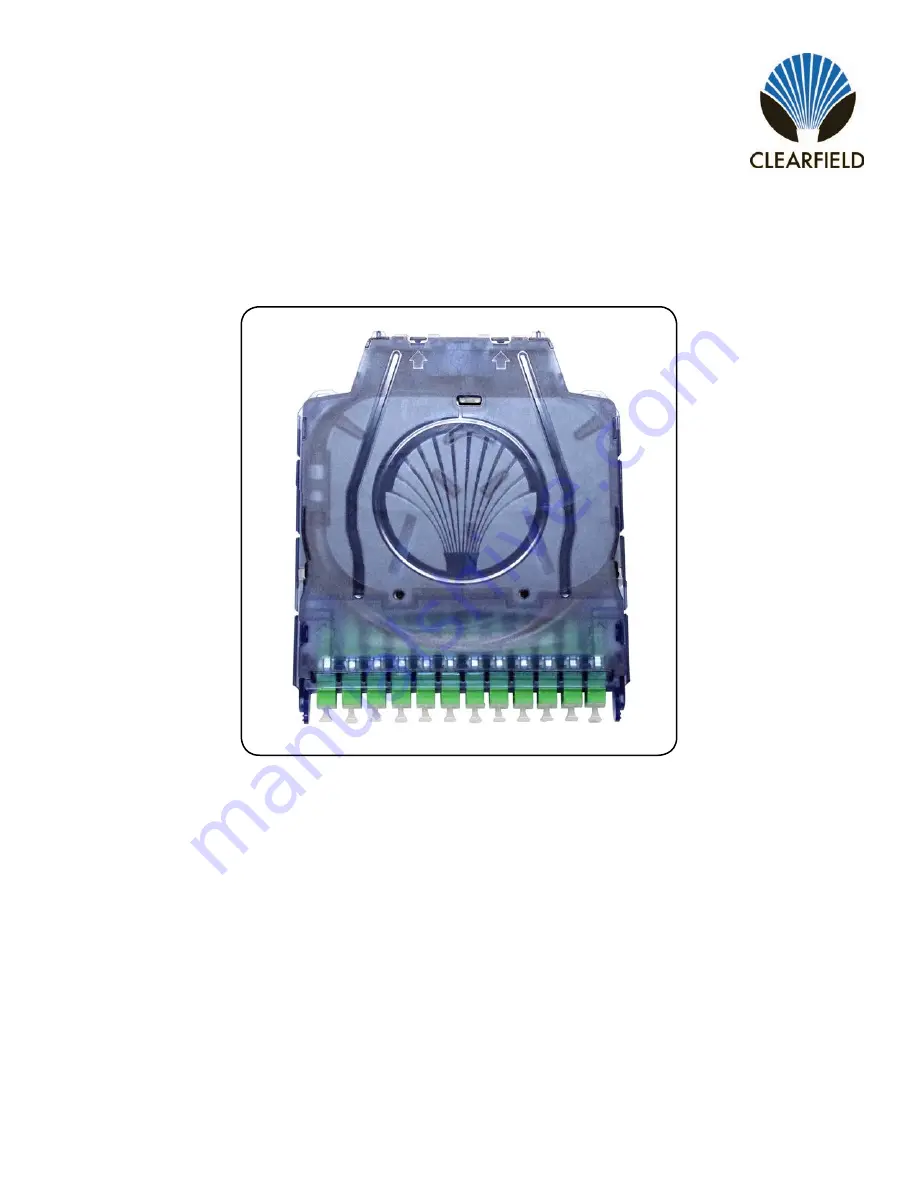
Page 6: ...he cable entrance points and method of slack storage are different Splicing loose tube or ribbon utilizing the standard entrance Splicing loose tube fiber utilizing the lower level buffer tube storage Splicing ribbon fiber utilizing lower level ribbon storage The Clearview Blue Cassette will arrive as shown including a strain relief boot as well as mounting ears and retaining screws plungers depen...
Page 7: ...ce tray cover Note For loose tube cassettes the fiber pigtail inside is composed of a ribbon that has been delaminated and fanned out You must remove the bottom slack storage cover in order to access the back of the tie down locations for the standard entrances as well as for access to the slack storage entrances The bottom slack storage cover is opened by squeezing the center section and pulling ...
Page 8: ...om slack storage cover hold the slack storage cover at 90 degrees and re insert the slack storage cover s hinges into the slots on the back of the cassette Grab the slack storage cover by the center section and use a finger to bend the cover towards the cassette sliding the tabs on the end of the slack storage tray cover into their places at the bottom of the cassette base highlighted here Push do...
Page 9: ...her side of the splice tray for a right exit Note Standard exit entrance is determined looking from the back of the cassette Slide the strain relief boot over the end of the buffer tube and push it down the tube over 3 feet Measure 3 feet back from the end of the buffer tube and mark the tube with a permanent marker Wrap one layer of grommet tape around the buffer tube behind your mark and trim th...
Page 10: ...and push it into the boot retainer at the standard entrance Secure the buffer tube down with the cable tie Trim the excess Note If using the right exit the fiber will need to be redirected Refer to the Right Rear Redirect section on page 27 for special routing instructions Proceed to the loose tube splicing section of this manual 6 7 8 Insert a cable tie or piece of wax string into the desired tie...
Page 11: ...for a right exit Note Standard exit entrance is determined looking from the back of the cassette 1 Measure 30 inches back from the end of the tight buffer cable and mark the cable with a permanent marker Note Due to the size of the cable a strain relief boot will not be used with tight buffer cable 2 Remove the outer jacket from the cable at the mark you made by carefully cutting a ring around the...
Page 12: ... be damaged 6 After the cable is secured to the cassette coil the tight buffer fibers in the cassette and proceed to the loose tube splicing section of this manual Note Of the 30 inches of 900 micron tight buffer fiber exposed 2 inches will be stripped and used for splicing The other 28 inches will be stored in the slack storage chamber of the splice tray Otherwise splicing will be performed in th...
Page 13: ... from the back of the cassette Ribbon Slide the strain relief boot over the end of the furcation tube Fold a piece of grommet tape over the tube just behind the end and trim the excess Feed 3 feet of ribbon fiber out of the end of the furcation tubing Insert a cable tie or piece of wax string into the desired tie down holes at the top of the cassette 1 2 3 4 Slide up the boot and push it into the ...
Page 14: ... relief boot over the end of the ribbon fiber and slide the boot over 3 feet down the length of the fiber 2 3 Slide the provided ribbon tie down soft tube side first over the end of the ribbon Heat the ribbon tie down into place 3 feet back from the end of the ribbon Note Never tie down bare unprotected ribbon fiber Insert a cable tie or piece of wax string into the desired tie down holes at the t...
Page 15: ... page 27 Note A strain relief boot is shown in every location but the cassette will include only one Opening the lower slack storage door to 90 degrees will allow you to lift the door away from the base 2R 1R 1L 2L 3R 3L Cable Entrance Method Slack Storage The Clearview Blue Cassette allows for roughly 8 feet of slack storage in its lower chamber The pictures shown in this section will mostly feat...
Page 16: ...the splice tray through the transition hole in the splice tray Note The fiber will need to be redirected during splicing refer to the Right Rear Redirect section on page 27 for special routing instructions Bottom View Top View Entrances 2L 1R 3R For cable entrances 2L 1R and 3R insert the buffer tube to be spliced into the bottom of the cassette as shown The buffer tube will extend into the splice...
Page 17: ... buffer tube Note More than one lap will not allow the cover to close properly and lie flat Insert a cable tie or length of wax string into the tie down holes at the top of the cassette which best fit your routing scheme Remove the outer jacket of the buffer tube at the mark you made Secure the buffer tube with the cable tie and trim the excess Note Push the cable tie head down to the side so it d...
Page 18: ...re your buffer tube slack in the base of the cassette 10 Begin by routing the buffer tube in a counter clockwise spiral pattern feeding the buffer tube in as you go around to ensure the buffer tube is pushed up flat against the previous layer The slack storage tray can store up to 8 feet of buffer tube Continue routing the buffer tube until you have stored the desired amount Note The buffer tube s...
Page 19: ...red cross the buffer tube over the coil at the top of the cassette and transition to the outside track of the buffer tube storage tray For entrance 2L the boot can then be slid up and inserted into the boot retainer For entrance 1R continue around the outside exit track and place the boot in the retainer at the exit For entrance 3R continue further around the exit track and place the boot in the r...
Page 20: ... store your buffer tube slack in the base of the cassette 10 Begin by routing the buffer tube in a clockwise spiral pattern feeding the buffer tube in as you go around to ensure the buffer tube is pushed up flat against the previous layer The slack storage tray can store up to 8 feet of buffer tube 11 Continue routing the buffer tube until you have stored the desired amount Note The buffer tube sh...
Page 21: ...red cross the buffer tube over the coil at the top of the cassette and transition to the outside track of the buffer tube storage tray For entrance 2R the boot can then be slid up and inserted into the boot retainer 13 14 For entrance 1L continue around the outside exit track and place the boot in the retainer at the exit 15 For entrance 3L continue further around the exit track and place the boot...
Page 22: ...rcation tubing This length of exposed ribbon must include 3 feet for splicing in the cassette splice tray as well as whatever amount of slack you wish to store Bring the ribbon through the transition hole in the splice tray Consult the loose tube storage section for information on which direction to route the ribbon depending upon your desired entrance Insert the ribbon through the ribbon tie down...
Page 23: ...direct section on page 27 for special routing instructions Refer to the ribbon splicing section of this manual and return to the next step once you are ready to store the remaining slack inside the cassette After you have spliced in the cassette and are ready to store your ribbon in the storage tray consult page 18 or page 20 depending upon entrance used for storage instructions Ribbon will store ...
Page 24: ...3L or 2R refer to the Right Rear Redirect section on page 27 for special routing instructions Note Standard exit entrance is determined looking from the back of the cassette Route the incoming fibers in the left chamber of the splice tray under the fiber management tabs Bring the ends of the fibers into the splicing area from the left side and trim to length Pull the fibers out of the splice tray ...
Page 25: ...m techsupport clfd net Manual 019389 Rev E July 2018 Insert the splice sleeves into the 2 x 6 splice chip six slots that hold two sleeves each one on top of the other as you proceed Note Clearfield recommends 40mm splice sleeves for the Clearview Blue Cassette especially when splicing 24 fibers Continue until all 12 fibers are spliced and loaded into the cassette 7 8 ...
Page 26: ... sleeves route the slack back into the right side of the splice tray The fiber will naturally cross over itself Continue routing the fiber until all the slack is properly stored Note Ensure the fiber is routed underneath all the fiber management tabs of the splice tray Proceed to routing the extra fiber slack on the left side into the splice tray in the same manner as the other side Replace the sp...
Page 27: ...er pigtail This fiber will need to be redirected in order to allow the ends of the incoming fiber and the pre loaded fiber pigtail to meet end to end in the splicing area of the splice tray Begin by pulling the pre loaded fiber pigtail out of the right side of the splice tray Following the arrows printed on the splice tray route the incoming fiber down into the right side of the tray and proceed t...
Page 28: ...ay Trim Here Bring the incoming fiber into the splicing area from the left and trim to length Store the pre loaded fiber pigtail back in the right side of the cassette Bring the pre loaded fiber into the right side of the splicing area and trim to length Pull both sets of fibers out of the tray Perform your splices as normal stacking the splice sleeves two high in the 6 slots of the splice sleeve ...
Page 29: ...oute the fibers on the left hand side of the cassette into the splice tray first being careful to keep all fibers underneath the fiber management tabs Proceed to routing the extra fiber slack on the right side into the splice tray in the same manner as the other side Replace the splice tray cover and cassette cover If utilizing the cassette s slack storage capabilities refer back to the slack stor...
Page 30: ...ength are required for splicing 24 fibers in the Clearview Blue Bring your buffer tube into the cassette per one of the entrance methods described previously Remove the pre loaded fiber pigtail from the splice tray 1 2 For cassettes using the left exit standard entrance or slack storage entances 2L 1R or 3R begin the splicing process as shown For right exit standard entrance cassettes or ones usin...
Page 31: ...the left splice sleeve chip and trim to length Remove the fiber from the tray Note Clearfield recommends to splice fibers 1 12 in the left splice sleeve chip However the placement of the 24 splices is up to you Just be careful to keep track of which fibers are going to which splice sleeve chip Route the second group of 12 fibers into the left slack storage chamber of the splice tray Bring them int...
Page 32: ...lice sleeve chip and cut them to length at the left splice sleeve chip so that they match them up with your first twelve fibers from the incoming buffer tube Remove the fibers from the tray Fibers 1 12 Fibers 13 24 Trim Here Trim Here Repeat the process on the right side with the two sets of twelve fibers from the pre loaded fiber pigtail 9 10 11 Route the second group of twelve fibers into the ri...
Page 33: ...correct lengths and pulled from the tray begin splicing fibers 1 12 and loading the corresponding splice sleeve chip Note Each splice sleeve chip features 6 slots which will hold 2 splice sleeves in each slot Once fibers 1 12 have been spliced and the splice sleeves placed in their holding location the cassette should look like the image shown Route the fibers on the right side coiling them into t...
Page 34: ...ice tray Splice fibers 13 24 in the same way placing the sleeves in the right splice sleeve chip Route the fibers on the left and right sides into their respective slack storage chambers Note Ensure that fibers do not cross over the adjacent splice sleeves as they travel to the slack storage chamber to avoid pinching fibers when the splice tray cover is installed Replace the splice tray cover and ...
Page 35: ...8 up to a max of 1x32 which requires two expansion rings The expansion ring is also available for in cassette splicing patch and splice methods If you wish to perform a 24 fiber splice in the Clearview Blue Cassette loose tube or ribbon while utilizing SC connectors the expansion ring makes that option available Note If your cassette features an expansion ring be careful when tipping the cassette ...
Page 36: ... Trim to length at the ribbon splice sleeve chip Bring the pre loaded ribbon fiber pigtail into the splicing area from the right side Trim to length at the ribbon splice sleeve chip Trim Here Splicing in the Cassette Ribbon Trim Here For cassettes using the left exit standard entrance or slack storage entances 2L 1R or 3R begin the splicing process as shown For right exit standard entrance cassett...
Page 37: ...e routed back inside the tray and under the fiber management tabs with ease after splicing Proceed to splicing 6 7 Place the ribbon splice sleeve into the ribbon splice sleeve chip again being careful to maintain the twists in the now spliced ribbons Route the two sides of the ribbons back into the left and right slack storage chambers You may need to flip over the ribbons to get the twists back t...
Page 38: ...d of your choice For cassettes using the left exit standard entrance or slack storage entances 2L 1R or 3R begin the splicing process as shown For right exit standard entrance cassettes or ones using slack storage entrances 1L 3L or 2R refer to the Right Rear Redirect section for special routing instructions Note Standard exit entrance is determined looking from the back of the cassette 1 Route th...
Page 39: ...trim to length at the ribbon splice chip 4 Trim Here Note Pay attention to which ribbon is flagged 1 and 2 The innermost ribbon will be flagged 1 Pull the incoming ribbons out of the left splice stray slack storage chamber Note It is important to maintain the twists in the ribbon that made up the loops while the ribbon was stored in the left chamber of the splice tray This will allow for the ribbo...
Page 40: ...________________ Manual 019389 Rev E July 2018 Repeat the process on the other side with the pre loaded ribbons remembering to maintain the twists in both ribbons Separate the ribbons taping ribbon 2 fibers 13 24 down to the table Make sure to maintain the correct number of twists in the ribbon Prep ribbon 1 fibers 1 12 and place it in the splicer to hold it in place 6 7 8 ...
Page 41: ...e to prevent it from flipping over either by placing it in the ribbon splice sleeve chip or the splicer s splice sleeve oven Proceed to splicing the two 2 ribbons together maintaining the twists 9 10 Place both splice sleeves in the ribbon splice sleeve chip 11 Prepare to route the ribbons into the two slack storage chambers of the splice tray On each side it is recommended to keep the two ribbons...
Page 42: ...ice work to coil the ribbons back into the slack storage chamber Note You may need to flip over the ribbons to get the twists back to the correct orientations to coil nicely back into the tray Repeat the process for the other side Note Make sure the fiber is routed fully underneath the splice tray fiber management tabs as shown Replace the splice tray cover and cassette cover If utilizing the cass...
Page 43: ...ils on the sides of the cassette 1 To attach the mounting ear onto the cassette align the channel on the side of the mounting ear with the t rail on the side of the cassette Press the mounting ear firmly against the t rail allowing the lever to flex back and the t rail to engage with the channel on the mounting ear 2 3 Slide the mounting ear up to the t rail until it comes to a stop and the lever ...
Page 44: ...taining screw will push into place in the hole located on the tab of the mounting ear Note Do not twist the retaining screw into place push the screw straight in Repeat the process for the other side and proceed to mounting the cassette 1 Retaining Screws 2 3 If the push pull plunger is not already installed insert the first piece of the push pull plunger grommet into the hole in the mounting ear ...
Page 45: ...lling the mounting ear off the cassette If you are attempting to remove the mounting ears from an Optical Component Cassette or any cassette which uses the Expansion Ring to increase its height such as the 24 SC Expansion Cassette the adapter plate will be held into place via locking pins These will prevent you from removing the mounting ears off of the front of the cassette In order to remove the...
Page 46: ...the Clearview Blue Cassette will mount into place with a ganging bracket Each section of ganging bracket which are stackable can hold two Clearview Blue Cassettes and are removable The ganging bracket utilizes the cassette s t rail to hold the cassette in place in conjunction with connection points on the back of the cassette Notice the channel on the inside of the ganging bracket meant for slidin...
Page 47: ... National 800 422 2537 www SeeClearfield com techsupport clfd net Manual 019389 Rev E July 2018 Engage the cassette s t rail with the channel in the ganging bracket and slide the cassette forward Push until the cassette snaps into place A second cassette will slide into place in the remaining slot of the ganging bracket 2 3 4 ...
Page 48: ...te blocks of any size though 12 is typical and what will be shown here Stack the cassettes you wish to gang together The Clearview Blue Cassette has four points along the outside of the cassette meant for securing the cassettes together one on each side behind the t rail and two on the back 1 2 Align the cassettes as best as possible and feed a cable tie up through all the cassettes you wish to ga...
Page 49: ...f the end face Learn the process of cleaning properly Note It is NOT recommended to use isopropyl alcohol to clean the end face Cleaning an SC LC Connector Cleaning the End Face Place one wiping paper on QbE 2 FiberSafe Cleaning Platen Figure 1 Apply small amount of precision cleaner about 1 in diameter with Electro Wash MX pen on to one end of the wipe Figure 2 Hold end face at a 90 degree angle ...
Page 50: ... the Adapter Itself Lightly moisten the fiber optic swab 2 5mm 38542F or 1 25mm 38040 by spotting a small amount about 1 of Electro Wash PX or Electro Wash MX pen onto the QbE Hold the tip of the swab onto the wetted area and hold for a count of 1 2 3 4 5 Insert the swab into the adapter to the connector press lightly against the connector twist 2 3 times remove and discard Dry with a second dry s...
Page 51: ...e 1 Figure 1 Figure 2 Figure 3 Hold end face at a 90 degree angle For APC connection adjust by slightly tilting the container or end face Angle is correct when no drag is felt on the end face Figure 2 Male Connector Lightly moisten one side of the fiber optic swab CC505F by spotting a small amount about 1 of Electro Wash PX or Electro Wash MX pen onto the QbE Hold the swab 1 side down to the wette...
Page 52: ...on of Clearfield Inc shall constitute the exclusive sole remedy for a breach of this limited warranty Clearfield shall not be liable under any circumstances for any special consequential incidental punitive or exemplary damages arising out of or in any way connected with the product or with agreement to sell product to buyer including but not limited to damages for lost profits loss of use or for ...
Page 53: ...supplied Every effort has been made to keep the information contained in this document current and accurate as of the date of publication or revision However no guarantee is given or implied that the document is error free or that it is accurate with regard to any specification Technical Support Clearfield Inc can be contacted for any issues that arise with the supplied product If you need to retu...