4. Cut hole where the
ClearPOWER
installation cable will attach.
5. Attach
ClearPOWER
installation cable to the Docking Station.
6. Screw lags into studs 80% on previously marked location.
7. Hang Docking Station using “Eyelet holes” that are pre-drilled and located on the back of the Docking
Station
8. Tighten lags completely.
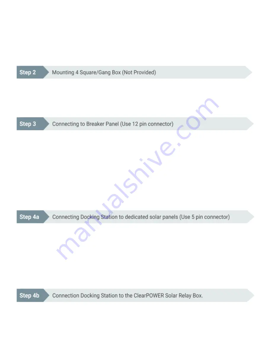
1. Fish other end of
ClearPOWER
installation cable to 4 Square location.
2. Attach 4 Square Box to ½” knock-out and secure using locking.
3. Mount 4 Square Box.
1. Identify 3 critical circuits to be backed-up by the
ClearPOWER
ClearPOWER P2.
2. De-energize panel breakers.
3. Run wires from the panel protected in conduit, Sealtite, Flex or other appropriate means to the 4 Square
Box.
4. Label and Mark wires according to the provided wiring diagram in order to easily match with the labeled
wires on the
ClearPOWER
installation cable.
5. Connect to corresponding wires on the
ClearPOWER
installation cable located in the 4 Square Box.
6. Connect corresponding wires (hot, neutral and ground) to the breakers following the provided wiring guide
and wire numbers.
7. Energize the breaker panel and test.
1. Run PV wire from the solar panels, through appropriate conduit, to the 4 Square Box.
2. Install disconnect to the PV power cables.
3. Ensure disconnect is off.
4. Follow the provided wiring guide connect PV power cables to the
ClearPOWER
installation cable in the 4
Square Box.
5. Turn disconnect switch on and energize the circuit.
6. Test
***Optional and purchased separately. Used for connecting to existing solar arrays with micro-inverters
and/or optimizers.
Summary of Contents for ClearPOWER P2
Page 1: ......


