background image


7.5m - Straw Harrow  

[23] 

4


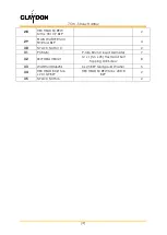
NYLOC NUT M16


18


5


PP50


Plastic Plug for 50mm Round Tube


2


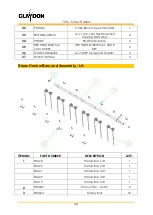
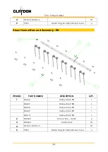
Straw Harrow Bars and Assembly - RH 


ITEM NO.


PART NUMBER


DESCRIPTION


QTY.


SHA06 

Harrow Bar 6 RH 


SHA07 

Harrow Bar 7 RH 


SHA08 

Harrow Bar 3 RH 


SHA09 

Harrow Bar 4 RH 


SHA10 

Harrow Bar 5 RH 

2


SH0603


Harrow Tine - 16mm


6


3


SH0604


Harrow Bolt


18


4


NYLOC NUT M16


18


5


PP50


Plastic Plug for 50mm Round Tube


2


Summary of Contents for Straw Harrow - 7.5m

Page 1: ...anual and Part s Manual Original Instructions Contact Details Claydon Yield O Meter Ltd Gaines Hall Wickhambrook Newmarket Suffolk CB8 8YA Tel 44 0 1440 820 327 Fax 44 0 1440 820 642 Email info claydondrill com www claydondrill com ...

Page 2: ...actor 7 4 1 Transportation 8 5 0 Straw Harrow Set up 9 5 1 Set Machine Level 9 5 2 Working Height 9 5 3 Field Use 10 6 0 Care and Maintenance 11 6 1 Lubricating Points 11 Part s Manual 7 5m Straw Harrow Spare Parts 14 Straw Harrow Front Chassis 15 Wing Assembly RH 17 Wing Assembly LH 20 Straw Harrow Bars and Assembly LH 22 Straw Harrow Bars and Assembly RH 23 Hydraulics Rake Angle 24 Hydraulics Wi...

Page 3: ...ON DOCUMENT IS NOT RETURNED THEN THE STRAW HARROW WARRANTY WILL BE VOID Straw Harrow Warranty Registration NAME ADDRESS CONTACT NUMBER DELIVERY DATE SERIAL NUMBER PLEASE ENSURE The Machine is washed off upon delivery to remove any road salt SIGNATURE PLEASE RETURN WITH A COPY OF YOUR INVOICE AND THE DELIVERY NOTE THE HYDRAULIC FREE FLOW SERVICE MUST BE PL THE HYDRAULIC FREE FLOW SERVICE MUST BE PL...

Page 4: ...re of all transport locks on the machine and knows how to operate them correctly The customer understands the correct sequence for folding and unfolding the machine The customer understands how to set the machine level front to rear The customer understands how to set the machine level left to right The customer understands how to adjust and set the operating height of the machine The customer und...

Page 5: ... stickers 7 5m Straw Harrow Figure 1 Position of Safety stickers on 7 5m Straw Harrows If any of the stickers become illegible or peel off new stickers can be ordered and attached in the appropriate position The stickers must not be removed Meaning of warning symbols and caution labels Read the operating manual carefully Prior to operating the machine the manual must be read fully and understood S...

Page 6: ...the wings watch out for overhead electricity cables Proceed with care in the event of leaking hydraulic fluid Defective hydraulic hoses or incorrectly seated hydraulic couplings can trigger unpredictable machine movements and cause injury Keep clear of slewing range There is an extreme risk of injury from slewing or folding machine parts Risk of crushing Gaps between components may become smaller ...

Page 7: ...eggs perfectly and as a result are right next to a perfect food source freshly germinated seeds when they hatch The purpose of this Operator s Manual is to comprehensively explain to the operator how to set up use and maintain the machine It is important that the operator reads this manual carefully to correctly set up use and maintain the machine safely For any further assistance or explanation p...

Page 8: ... including when the wings are unfolded BEWARE OF OVERHEAD OBSTRUCTIONS when the machine is folded up in the transport position Ensure all bolts are retightened after the first eight hours of use Prior to transport ensure the hydraulic tap is in the lock position adjacent to the hydraulic pipes to prevent the wings unfolding Persons are forbidden to ride on the machine Do not work underneath suspen...

Page 9: ... Tractor connections The following labels Figure 4 can be found located on the front of the Straw Harrow these labels specify the corresponding hydraulic connections and there color coded indicators Folding cylinder Tine adjustment Figure 4 Labels for hydraulic services Once the Straw Harrow is attached and at the correct working height the top link should be set at an angle in which the convergen...

Page 10: ...G THE MACHINE UP N B ensure sufficient clearance is present between the rear of the Straw Harrow and the ground prior to folding Once folded turn the hydraulic tap parallel to the cylinder to lock the wings in the upright position Figure 6 To unfold the wings turn the hydraulic tap in the opposite direction and operate the spool valve Never transport along public highways without isolating the fol...

Page 11: ...ltered for aggressiveness from the cab with the hydraulic rake angle adjustment For chopped OSR or Bean stubble the rake angle can be at maximum if so required this position is most aggressive and moves the most soil Figure 7 However on chopped Wheat or Barley stubble the tines will need to be angled back to allow the straw to flow through the machine without blocking up Figure 7 Aggressive Rake A...

Page 12: ...s can be set to a very aggressive angle to maximise soil movement You should pull the Claydon Straw Harrow as quickly as you can within reason From time to time very rarely the Straw Harrow can catch a lump or a tramline and start to bounce in this scenario you should slow down or stop until the machine has settled and then carry on as normal To avoid this completely it is recommended that a small...

Page 13: ...retightened after the first eight hours of use 6 1 Lubricating Points Lubrication should be performed using multi purpose grease on a daily basis An overview of the 7 5m Straw Harrow can be seen in Figure 9 with the identification numbers corresponding to the details of the lubrication points in Figure 10 N B Lubrication should also be placed on the Harrows top link pin to prevent excessive wear f...

Page 14: ...2 Lubrication Points to be Greased Daily 1 Folding cylinder rod end 2 Left wing pivot pin 3 Right wing pivot pin 4 Right wing pivot pin 5 Folding ram base end 6 Left wing pivot pin Figure 10 Details of lubrication points ...

Page 15: ...7 5m Straw Harrow 13 7 5m Part s Manual ...

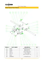
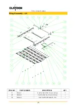
Page 16: ...ER DESCRIPTION QTY 1 SHA15 Straw Harrow Front Chassis 1 2 SHA71 Wing Assembly RH 1 3 SHA70 Wing Assembly LH 1 4 SH0415 Clamping Plate No Locating Holes 2 5 SH0411 Clamping Plate 2 6 HEX HEAD BOLT M16 x 200 10 9 BZP 16 7 PLAIN WASHER M16 FORM A BZP 32 8 NYLOC NUT M16 16 ...

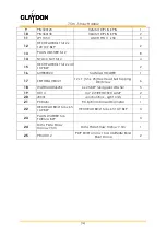
Page 17: ...t Chassis ITEM NO PART NUMBER DESCRIPTION QTY 1 SHA01 HEADSTOCK W ASSY 1 2 SHA02 BEAM ASSY RH 1 3 SHA03 BEAM ASSY LH 1 4 SHA16 Harrow Folding Ram 1 5 SH1103 Pivot Washer 2 6 SHA12 Big Folding Ram Pin 2 7 SHA11 2 8 DU808560 DU BUSH 80 X 60 8 ...

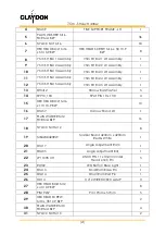
Page 18: ...HOLDER 1 17 SELFDRILLHEX121 12 x 1 5 5 x 25 Hex Head Self Tapping Drill Screw 6 18 WASHMUDM625Z 6 x 25 BZP Mudgaurd Washer 5 19 HC14 1 4 2 WIRE HOSE CLAMP 2 20 JB001 Junction Box Light Units 1 21 PC8MM P Clip 8mm Closed Diameter 1 22 HEX HEAD BOLT M6 x 65 10 9 BZP HEX HEAD BOLT M6 x 65 10 9 BZP 3 23 PLAIN WASHER M6 FORM A BZP 3 24 Data Plate Straw Harrow 7 5m Data Plate Straw Harrow 7 5m 1 25 PR 4...

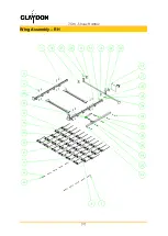
Page 19: ...7 5m Straw Harrow 17 Wing Assembly RH ...

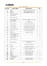
Page 20: ... 5m SH Bar 9 RH Assembly 1 11 7 5m SH Bar 10 RH 7 5m SH Bar 10 RH Assembly 1 12 SH0412 Harrow Bar Washer 5 13 SP910_100 SPLIT PIN 10 x 100 4 14 HEX HEAD BOLT M16 x 110 10 9 BZP 10 15 PLAIN WASHER M12 FORM A BZP 16 16 NYLOC NUT M12 8 17 MB423X423RW Marker Board 423mm x 423mm Red White 1 18 SHA17 Angle Adjustment Ram 1 19 SHA05 Angle Adjustment Bar 1 20 LP11X35 UH LINCH PIN 11 x 35mm Under Head Linc...

Page 21: ... M10 FORM A BZP 4 30 NYLOC NUT M10 2 31 PC8MM P Clip 8mm Closed Diameter 7 32 SELFDRILLHEX121 12 x 1 5 5 x 25 Hex Head Self Tapping Drill Screw 8 33 WASHMUDM625Z 6 x 25 BZP Mudgaurd Washer 5 34 HEX HEAD BOLT M6 x 20 10 9 BZP HEX HEAD SCREW M6 x 20 8 8 BZP 2 35 NYLOC NUT M6 2 ...

Page 22: ...7 5m Straw Harrow 20 Wing Assembly LH ITEM NO PART NUMBER DESCRIPTION QTY 1 SHA61 Centre Bar With Hose Clamps 1 2 SHA62 Centre Bar No Hose Clamps 1 3 SHA60 TINE SUPPORT FRAME RH 1 ...

Page 23: ...1 13 SH0412 Harrow Bar Washer 5 14 SP910_100 SPLIT PIN 10 x 100 4 15 HEX HEAD BOLT M16 x 110 10 9 BZP 10 16 SHA57 Harrow Stand LH 1 17 PLAIN WASHER M12 FORM A BZP 16 18 NYLOC NUT M12 8 19 MB423X423RW Marker Board 423mm x 423mm Red White 1 20 SHA17 Angle Adjustment Ram 1 21 SHA05 Angle Adjustment Bar 1 22 LP11X35 UH LINCH PIN 11 x 35mm Under Head Linch Pin 5 23 RL002 LED Bolt on Rear Light 1 24 SHA...

Page 24: ...HEAD BOLT M6 x 20 10 9 BZP HEX HEAD SCREW M6 x 20 8 8 BZP 2 36 WASHMUDM625Z 6 x 25 BZP Mudgaurd Washer 5 37 NYLOC NUT M6 2 Straw Harrow Bars and Assembly LH ITEM NO PART NUMBER DESCRIPTION QTY 1 SHA23 Harrow Bar 1 LH 1 SHA22 Harrow Bar 2 LH 1 SHA21 Harrow Bar 3 LH 1 SHA20 Harrow Bar 4 LH 1 SHA19 Harrow Bar 5 LH 1 2 SH0603 Harrow Tine 16mm 6 3 SH0604 Harrow Bolt 18 ...

Page 25: ...ow Bars and Assembly RH ITEM NO PART NUMBER DESCRIPTION QTY 1 SHA06 Harrow Bar 6 RH 1 SHA07 Harrow Bar 7 RH 1 SHA08 Harrow Bar 3 RH 1 SHA09 Harrow Bar 4 RH 1 SHA10 Harrow Bar 5 RH 1 2 SH0603 Harrow Tine 16mm 6 3 SH0604 Harrow Bolt 18 4 NYLOC NUT M16 18 5 PP50 Plastic Plug for 50mm Round Tube 2 ...

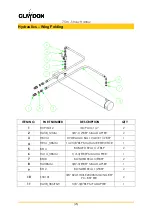
Page 26: ...SEAL 3 8 BSP 7 3 HA14 _38MM 1 4 3 8 BSP MM ADAPTER 7 4 HCPISO12 ISO PLUG 1 2 2 5 BS12 BONDED SEAL 1 2 BSP 2 6 HA14 _12MM 1 4 1 2 BSP MM ADAPTER 2 7 HT14BSP MMM Tee 1 4 BSP MALE 60 CONE 1 8 SH4002 1 4 R2AT HOSE 1200MM LONG BSP STR BSP 2 9 SH4003 1 4 R2AT HOSE 2000MM LONG BSP 90 BSP 2 10 SH4001 1 4 R2AT HOSE 3850MM LONG BSP 90 BSP 2 ...

Page 27: ...ER 2 3 HBV14 HYDRAULIC BALL VALVE 1 4 BSP 1 4 HR14 _38MM 1 4 3 8 BSP MM 1MM RESTRICTOR 1 5 BS14 BONDED SEAL 1 4 BSP 2 6 HA14 _38MM 1 4 3 8 BSP MM ADAPTER 1 7 BS38 BONDED SEAL 3 8 BSP 2 8 HA38MM 3 8 3 8 BSP MM ADAPTER 1 9 BS12 BONDED SEAL 1 2 BSP 2 10 SH4101 3 8 R2AT HOSE 2300MM LONG BSP 90 BSP STR 2 11 HA38_38MFSW 3 8 3 8 BSP MF ADAPTER 1 ...

Page 28: ...7 5m Straw Harrow 26 Appendix A Declaration of Conformity ...

Reviews: