Mounting diagrams
4
Detailed diagram for remote control switch
41001304 Iss 01
Fig 8
Page 1: ...pply or subject to misuse neglect damage or modified or repaired by any person not authorised by us This guarantee is offered to you as an extra benefit and does not affect your legal rights The corre...
Page 2: ...t Thermal cut out There are 2 thermal cut outs protecting the heater positioned along the heater box These cut outs are connected in series and each or both may operate in the event of fan failure or...
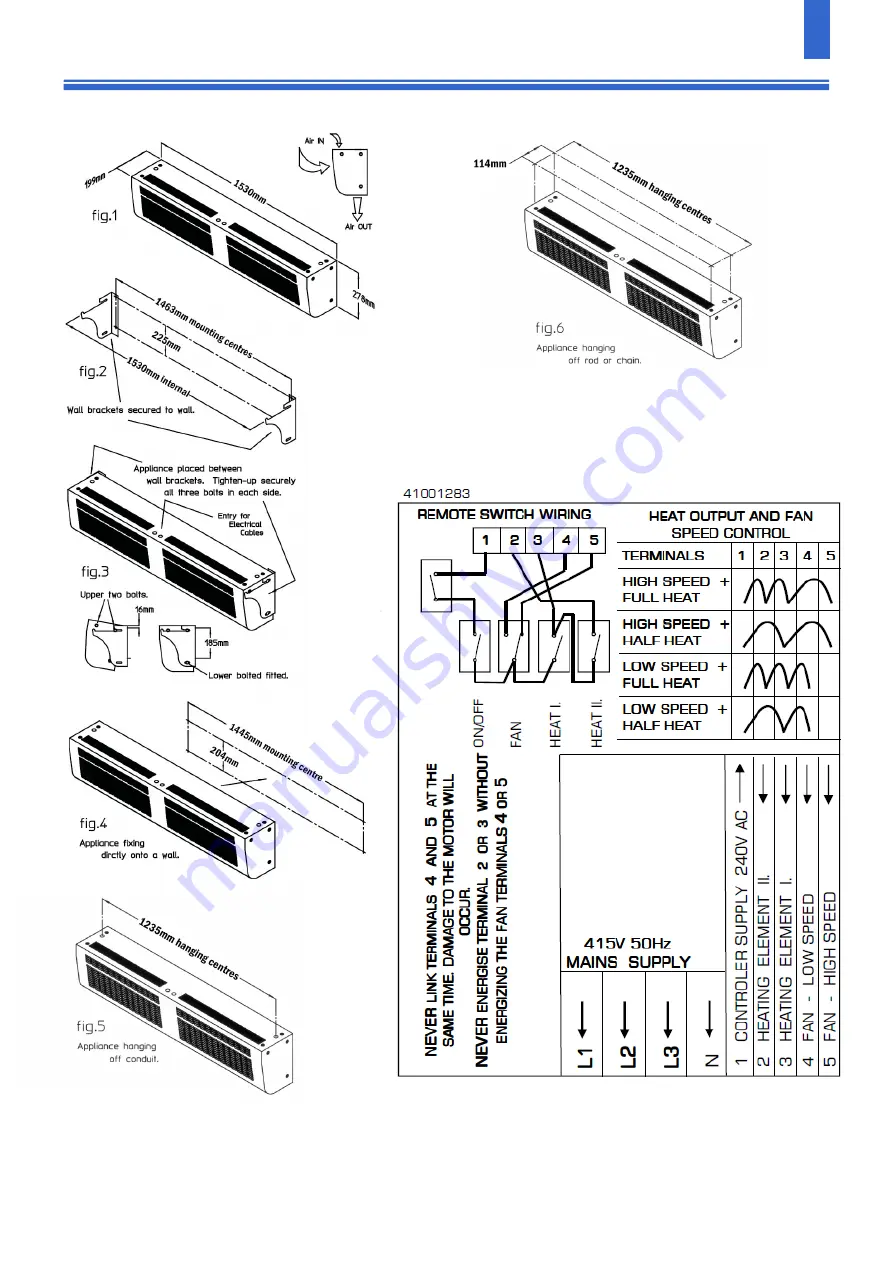
Page 3: ...The fitting of the lower bolts in each side locks the ap pliance to the brackets Tighten up securely all 3 bolts in each side 2 DIRECTLY to a suitable vertical wall or bearers Using 4 x No 12 wood scr...
Page 4: ...Mounting diagrams 4 Detailed diagram for remote control switch 41001304 Iss 01 Fig 8...
Page 5: ...tected by two fuses which have a 3 amp rating Ensure that any replacement is of the correct size and rating Spares It is essential when ordering spares or replacement parts to state the model number C...
Page 6: ...Equipment Products Limited Thornton Industrial Estate Milford Haven Pembrokeshire SA73 2RT Tel 01646 692172 Fax 01646 695195 Email technical consortepl com Web www consortepl com Operation hours Mon...