background image


21


947226 

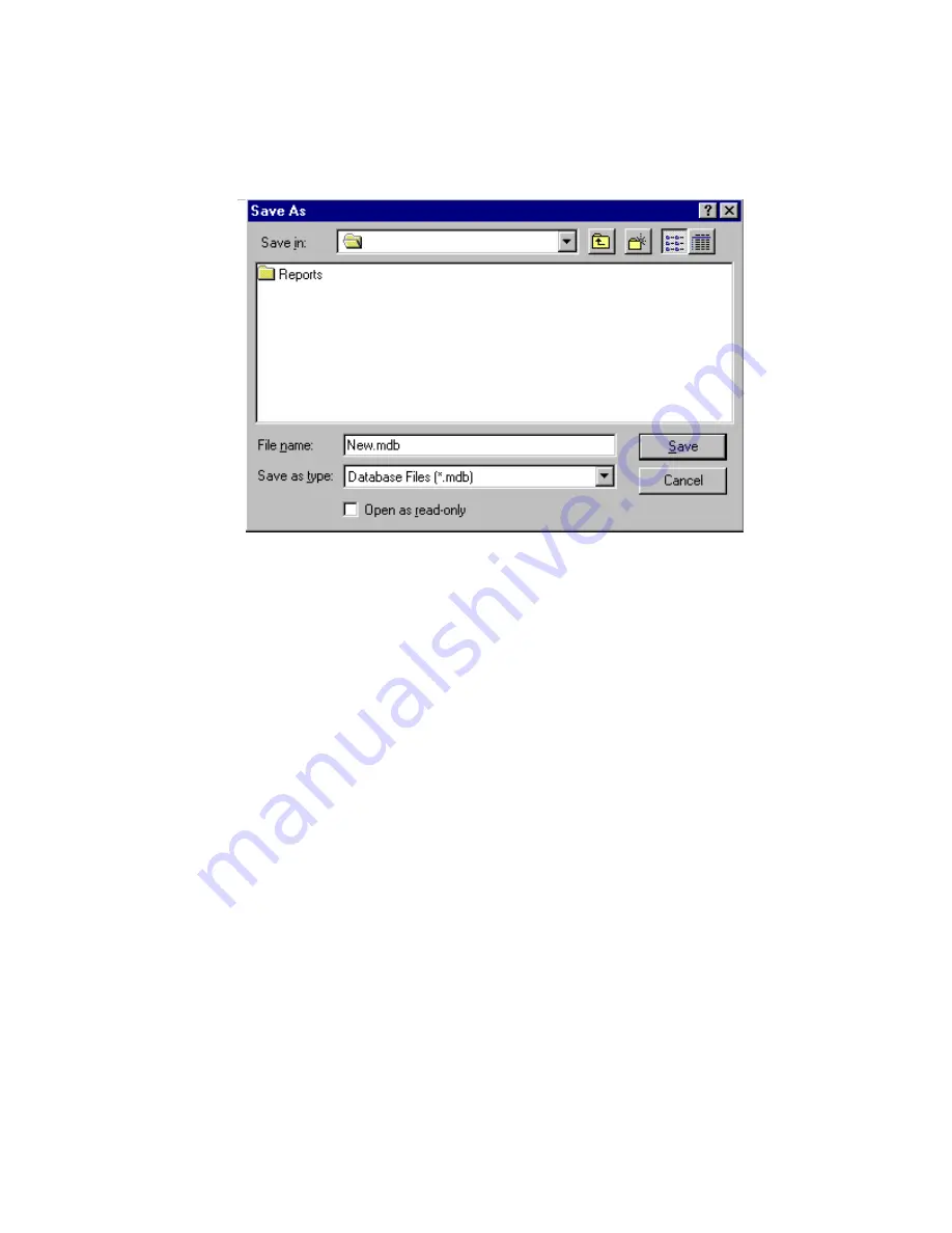
Save Programmed Data to a File  

When the programming selections are complete, click on the 

File 

menu option


to access the pull-

down menu and select

 Save

.  Define fine name and location and press 

Save


COMMUNICATING WITH THE VC-24 

Communicating with the VC-24 allows sending and receiving of user programmed data, Setting 
of System Date and Time, and reading the revision numbers of the system firmware. 
 
Once system programming is complete, this data must be downloaded to the VC-24 System.  
This communication can be accomplished through two methods: 

 
Initiating Communications 

Direct Connect

 (PC is on site with the VC-24 System - can be accessed via RS232 cable). 

To Connect:  
Connect cable from the VC-24 to the PC being used. 
Set up Com Port (see Set Up Com Port Section). 
Connection complete. 

 
Modem Connect 

(PC is off site or can only be accessed using phone lines to communicate). 

To Connect: 
Set up modem (See VCMDM user manual). 
Set up Com Port (See Set Up Com Port Section). 
Select Dialing Method 


Modem Connect  


Manual Connect  


A

VC-24

Summary of Contents for VC-24

Page 1: ...up call and all call pages Each station can be programmed for one way or two way communication The stations may be grouped into one way page groups The system also provides the ability for a remote speaker location equipped with a call button to call the attendant location The attendant receives calling speaker identification when using a Caller ID equipped telephone or a Caller ID display The VC ...

Page 2: ...ll Programmable class of service Time sync output Custom page groups Enhanced Caller ID Flexible Architectural numbering plan Interface to the PC Programming Tool Store user data to EEROM Real time clock for SMDR printer Auto detect for Com Port or Modem Auto adjust for Daylight Savings Time Evacuation tone to specified groups Time tones to specified groups Read software firmware revision numbers ...

Page 3: ...riority page level AUXILIARY CONTACTS Contact Closures are available on Zones 21 22 23 and 24 strike plates Main Unit Each contact operates when the respective zone number is dialed and the key is pressed twice Remote Signaling Closure follows ring pattern 250 mA max 24 Vdc PAGE PRIORITY It is possible for multiple inputs to request an audio connection to a speaker at the same time When a conflict...

Page 4: ... NOTE This unit provides an option for disabling Talkback Alert Tone and Repeating Privacy Tones Check local privacy regulations prior to disabling these tones Power Connections Use a cord set consisting of a minimum 18 AWG cord and grounding type attachment plug rated a minimum of 15A 250V The cord set should have the appropriate safety approvals for the country in which the equipment will be ins...

Page 5: ...2 R115 Handsfree Speaker to Phone Level Handsfree Phone to Speaker Level Background Music Level External Tone Source Level All Call Adjust Volume Attendant Level Override Port Page Level Internal Tone Source Level P3 P6 P7 P8 P10 45 ohm Speakers See Figure 2 Call In Switch Inputs See Figure 2 System Connections See Figure 2 Expansion Unit Connector RS232 Serial Port for SMDR DB9 Connector FIGURE 1...

Page 6: ...vate Dry Priority Activate Inhibit Inhibit Group 2 38 13 39 14 40 15 41 16 42 17 43 18 BK G G BK BK BR BR BK BK S S BK Y BL BL Y Y O O Y Y G G Y T STA 13 R STA 13 T STA 14 R STA 14 T STA 15 R STA 15 T STA 16 R STA 16 T STA 17 R STA 17 T STA 18 R STA 18 38 13 39 14 40 15 41 16 42 17 43 18 BK G G BK BK BR BR BK BK S S BK Y BL BL Y Y O O Y Y G G Y INA13 INB13 INA14 INB14 INA15 INB15 INA16 INB16 INA17...

Page 7: ...W O O W 28 3 W GR GR W BACKGROUND MUSIC CONNECTION P7 Connecting Block P7 Connecting Block Low Level Music Source 47 22 48 23 49 24 50 25 46 21 47 22 48 23 49 24 INA 21 INB 21 INA 22 INB 22 INA 23 INB 23 INA 24 INB 24 STATIONS 21 24 TSTA 21 RSTA 21 TSTA 22 RSTA 22 TSTA 23 TSTA 24 RSTA 24 RSTA 23 External Signalling Device STATIONS 1 20 Door Plate Speaker Pushbutton Block P3 Speaker Outputs Block P...

Page 8: ... Block 30 5 32 7 34 9 Signal Out V 9927A 1 8 Com EXTERNAL TONE SOURCE USING A V 9927A NOTE External tone source requires programming option to enable feature See Table 1 SW3 8 W S S W R O O R R BR BR R 31 6 33 8 Control from time clock Emergency Closure Normally Open Switch 2 2 3 3 5 7 DB9 Female DB25 Male To P10 VC 24 Control Unit Baud Rate 9600 8 bit no parity 1 stop bit SMDR PRINTER PORT CABLE ...

Page 9: ...Y Y O O Y Y BR BR Y P7 Connecting Block 43 18 44 19 P7 Connecting Block 43 18 44 19 P7 Connecting Block 43 18 44 19 NOTE Global all call page requires programming option to enable feature GLOBAL ALL CALL PAGE FROM ATTENDANT DIAL UP VC 24 1 VC 24 2 VC 24 3 Y G G Y Y BR BR Y Y G G Y Y BR BR Y Y G G Y Y BR BR Y P7 Connecting Block Tel System Page Port SW4 OFF Telephone SW4 ON OR 35 10 36 11 OVERRIDE ...

Page 10: ...mp V 1092 26 1 27 2 28 3 To Enable Feature strap must remain across pair when unit is powered CLOCK SYNC INPUT 45 20 Master Clock Y S S Y P7 Connecting Block Master Clock must make contact closure at 0200 Hours TSTA1 RSTA1 TSTA2 RSTA2 TSTA3 RSTA3 INA1 INB1 INA2 INB2 INA3 INB3 ONE WAY ONLY ...

Page 11: ...Operating System The Programming Tool is 32 bit and requires Windows 95 Windows 98 or Windows NT 4 0 The programming tool software is furnished on 1 4 MB disks and must be installed to the hard drive To install the software On the taskbar click the Start button Insert disk 1 Select Run Type a Setup Assuming a is the disk drive being used Follow on screen instructions for full installation changing...

Page 12: ...guration screen is displayed to allow selection of the installed components within the system Select one of the following from the list For a 24 station system select Main Board For a 48 station system select Main Board Expansion 1 For a 72 station system select Main Board Expansion 1 2 For a 96 station system select Main Board Expansion 1 2 3 Press OK to accept the present selection or Cancel to ...

Page 13: ...below The Programming Window allows each option to be accessed by selecting the option and pressing Open or by double clicking on the selected option All functions can be listed at once by pressing Open All All of the options accessed through the Programming Window can also be accessed from the pulldown menus ...

Page 14: ...be displayed on the phone or Caller ID unit if provided as part of the system The Edit Station Entry allows a CLID description to be entered for each station Example 105 would be the Arch and MR HALL would be the CLID description 15 character limit The Delete Station Entry allows removal of selected architectural and CLID descriptions Auto Numbering assigns the Arch in sequential order The beginni...

Page 15: ...ns Group 1 Stations 1 2 3 4 5 6 Main Board Group 2 Stations 7 8 9 10 11 12 Main Board Group 3 Stations 13 14 15 16 17 18 Main Board Group 4 Stations 19 20 21 22 23 24 Main Board Group 5 Stations 25 26 27 28 29 30 Expansion 1 Group 6 Stations 31 32 33 34 35 36 Expansion 1 Group 7 Stations 37 38 39 40 41 42 Expansion 1 Group 8 Stations 43 44 45 46 47 48 Expansion 1 Click on the tab of the desired fe...

Page 16: ...ly are moved to the top of the priority list to be answered first Normal Emergency Calls from stations programmed as Normal Emergency are received in the queue as they are made 1 button press from the station the call is received as a normal call 4 button presses from the station the call is received as an emergency call Normal Only Calls from stations programmed as Normal Only are received in the...

Page 17: ... displayed There are 4 Custom Page Groups available Select the Page Groups to receive custom paging by clicking on the desired box Each Custom Page Group can contain all groups or a combination of groups Example Custom Page Group 50 could contain page groups 1 2 and 3 and Custom Page Group 52 could contain page groups 1 2 7 and 8 Select OK after all desired page groups are defined ...

Page 18: ... Click Open Displays Schedule 1 menu Choose which days schedule is to be active Select Add New Event Screen menu will be shown Select Start Time Select which Relay Type you want to follow the Schedule and Select the Relay Duration of the contact closure Select which Page Group s tone should go to Select Save NOTE The contact closure pairs 13 14 15 16 on the system punchdown block should be wired t...

Page 19: ...options and click on OK to exit this screen The options are described in more detail in the Control Unit VC 24 document or select Help from the pull down menu for on screen details The Dip Switch button displays the dip switch equivalent see next page of the options selected with the programming tool Note that SW2 and SW3 are not used with the VC 24 System ...

Page 20: ...20 947226 Dip switch equivalent of programmed options ...

Page 21: ...e system programming is complete this data must be downloaded to the VC 24 System This communication can be accomplished through two methods Initiating Communications Direct Connect PC is on site with the VC 24 System can be accessed via RS232 cable To Connect Connect cable from the VC 24 to the PC being used Set up Com Port see Set Up Com Port Section Connection complete Modem Connect PC is off s...

Page 22: ... connect is being used make sure modem is installed and working properly Modem Connect From the Programming Tool select File Modem and then Modem Connect The screen below appears Enter the number to dial or select a phone number from the list displayed Numbers can be added edited or deleted from the list Up to 10 numbers can be stored Once the desired phone number is displayed in the Number to Dia...

Page 23: ...will be sent to the VC 24 System If no file is open when Send Data to VC 24 is selected the screen appears to allow selection of the data file to be opened and downloaded to the VC 24 Highlight the desired file and click on OK Receive Data from VC 24 From the main menu select Receive Data from VC 24 This will take place automatically If you are not allowed to select Receive Data from VC 24 close t...

Page 24: ...atic DST Adjustment can be enabled or disabled here Read Software and Firmware Revision Numbers This feature is accessed through the Help menu Select Help then About This option provides information for all processors Reminder The PC must be connected to the system to access this information Ending Communications Direct Connect No action required just unplug cable Modem Connect From the pulldown m...

Page 25: ...ptions for printing This screen shows all items selected for printing WINDOW The pull down menu titled Window allows several screens to be closed at once Instead of going through several open screens closing them individually select Window Close All or select the screens individually from the pull down window HELP The Help pull down menu provides on screen definition of elements provided by the VC...

Page 26: ...26 947226 A EXIT Select Exit from the File pull down to close the Programming Tool VC 24 VC 24 ...

Page 27: ... or all call pages are cancelled and the phone is connected to the attendant Override Page Port When a phone connected to the override page port goes offhook it is immediately connected to all speakers for a one way page Any existing handsfree or one way pages will be placed at the top of the queue for reconnection when the priority phone releases The attendant phone receives a repeat beep tone al...

Page 28: ... as long as connected Station 1 code 101 station 2 102 station 24 code 124 Page Codes Dial Code Groups 1 2 3 4 10 external all call multiple VC 24s 11 system all call 12 14 60 Example 60 71 73 61 62 70 71 72 73 92 Set Time hh mm ss 93 Cancel Emergency Tone during 1 way page Mute page while waiting for Meet Me during any connected call Disconnect current call connect to next queued call or receive ...

Page 29: ...rials and workmanship under conditions of normal use and Service for a period of two years from the date of shipment The obligation under this warranty shall be limited to the replacement repair or refund of any such defective device within the warranty period provided that 1 inspection by Valcom Inc indicates the validity of the claim 2 the defect is not the result of damage misuse or negligence ...

Page 30: ...e with multiple VC 24 systems that require all call and or priority pages to be broadcast to all interconnected systems Global Priority Activate 42 17 Control pair for use with multiple VC 24 systems that require priority pages to be broadcast to all interconnected systems Inhibit 37 12 If a single line telephone is desired for Meet Me Answer a single line A lead control telephone and a 5 1K ohm r...

Reviews: