background image

7

Parts & Service: 020 8988 7400 / E-mail: [email protected] or [email protected]

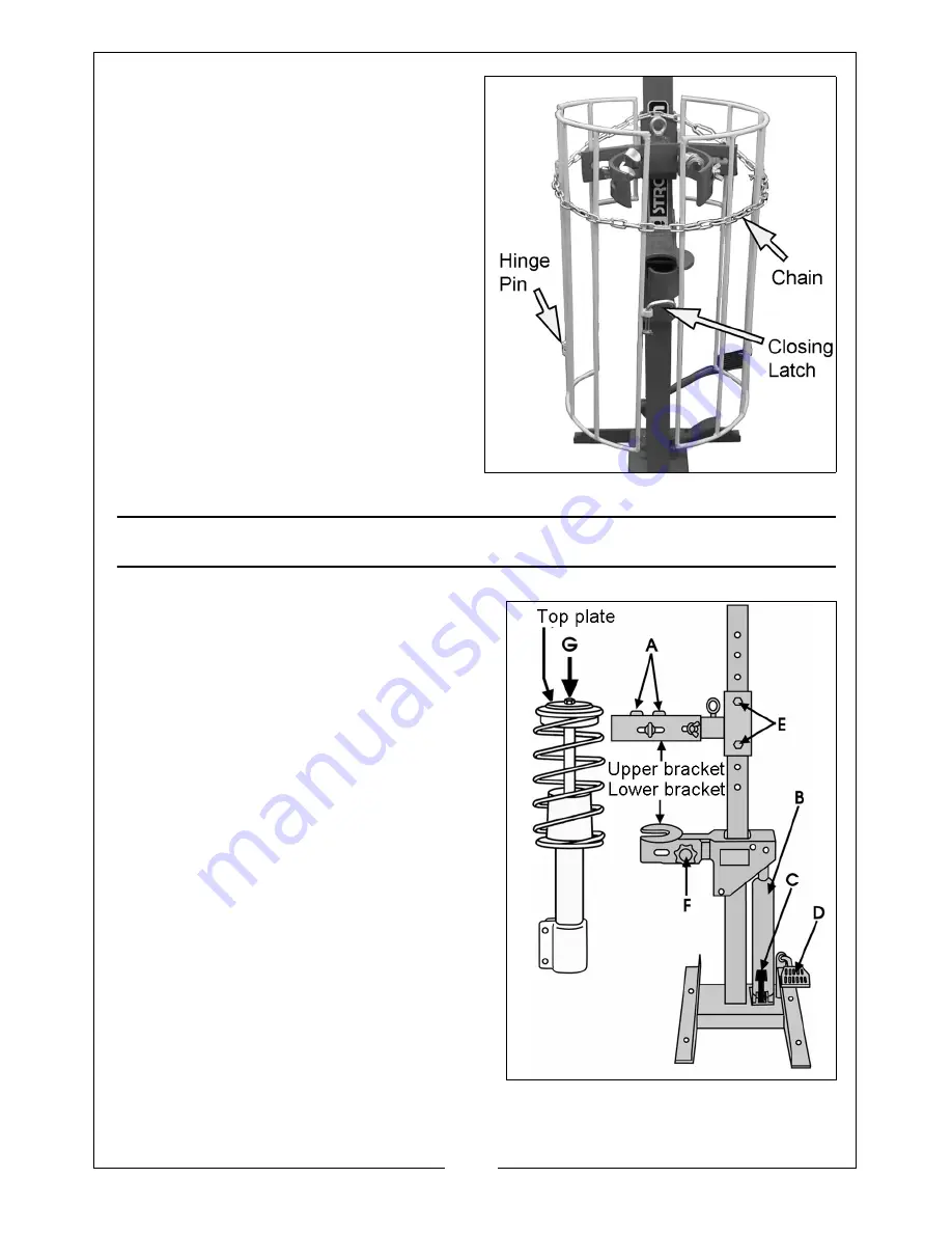
2. Add the outer guards to the inner 

guards, locating them using the 
hinge pins supplied and lock with 
split pins.

3. Fit the closing latch to the guards.

4. Before operating the compressor, 

the safety chain should be 
wrapped around the inner and 
outer guards as shown, 
connecting the two chain ends 
with the snap hook.

OPERATION

1. Press and hold down the release 

valve pedal ‘C’ to lower the ram to 
its lowest position.

2. Hinge the upper brackets back,

3. Slide the suspension leg into the 

lower bracket and clamp in place 
using the clasp and knob ‘F’. Do not 
overtighten - it should only be firm.

4. Position the upper bracket so that 

the two clamps ‘A’ fit snugly and 
squarely around the spring coils, as 
near to the top of the assembly as 
possible.

It may be necessary to remove the 

two pins securing the upper bracket 
assembly ‘E’ and slide the bracket up 
or down by the appropriate amount 
in order to locate the clamps ‘A’ 
correctly. Ensure the pins ‘E’ are 
locked by the R-clips before 
proceedin

g.

Summary of Contents for SSC1000G

Page 1: ...OPERATION MAINTENANCE INSTRUCTIONS ORIGINAL INSTRUCTIONS GC0718 ISS1 STRUT SPRING COMPRESSOR MODEL NO SSC1000G PART NO 7630030...

Page 2: ...a period of 12 months from the date of purchase Please keep your receipt as proof of purchase This guarantee is invalid if the product is found to have been abused or tampered with in any way or not...

Page 3: ...ying pressure ensure the workpiece is secure and stable Always clean up spills of hydraulic oil immediately as this can be dangerous in a workshop environment Do not allow any person who is unfamiliar...

Page 4: ...g transit and that all components are present Should any loss or damage become apparent please contact your CLARKE dealer immediately The following items should be present in the crate 1 Frame ram ass...

Page 5: ...ssor should not be stored where it will be open to the elements as severe weather conditions will damage the hydraulic parts 1 With the help of an assistant attach the base supports to the frame using...

Page 6: ...hydraulic ram and securing with the set screw 5 Fit the corresponding upper bracket to the column securing at the required height with the pins and R clips The removable pins provide several height se...

Page 7: ...ld down the release valve pedal C to lower the ram to its lowest position 2 Hinge the upper brackets back 3 Slide the suspension leg into the lower bracket and clamp in place using the clasp and knob...

Page 8: ...the suspension leg whilst loosening the lower bracket using the locking knob F The suspension leg may then be removed 10 Reassembly of the suspension leg is in reverse order MAINTENANCE ROUTINELY A vi...

Page 9: ...ny air bubbles Top up the hydraulic oil to the lower level of the filler plug with CLARKE hydraulic oil Part No 3050830 TROUBLESHOOTING Problem Probable Cause Remedy Pump will not work Dirt on seals w...

Page 10: ...is oil products Never throw away used oil with domestic refuse or flush it down a sink or drain Collect any oil in a leak proof container and take it to your local waste disposal site Should hydraulic...

Page 11: ...ase Support 18 Circlip 3 Main Frame 19 Saddle 4 Fixing Knob 20 Screw 5 Strut Clasp 21 Hydraulic Ram Assembly 6 Locating Pin 22 Bolt 7 Sleeve 23 Actuating Pedal 8 Lower Strut Holder 24 Bolt 9 Circlip 2...

Page 12: ......

Reviews: