OPERATION & MAINTENANCE
INSTRUCTIONS
LS0913
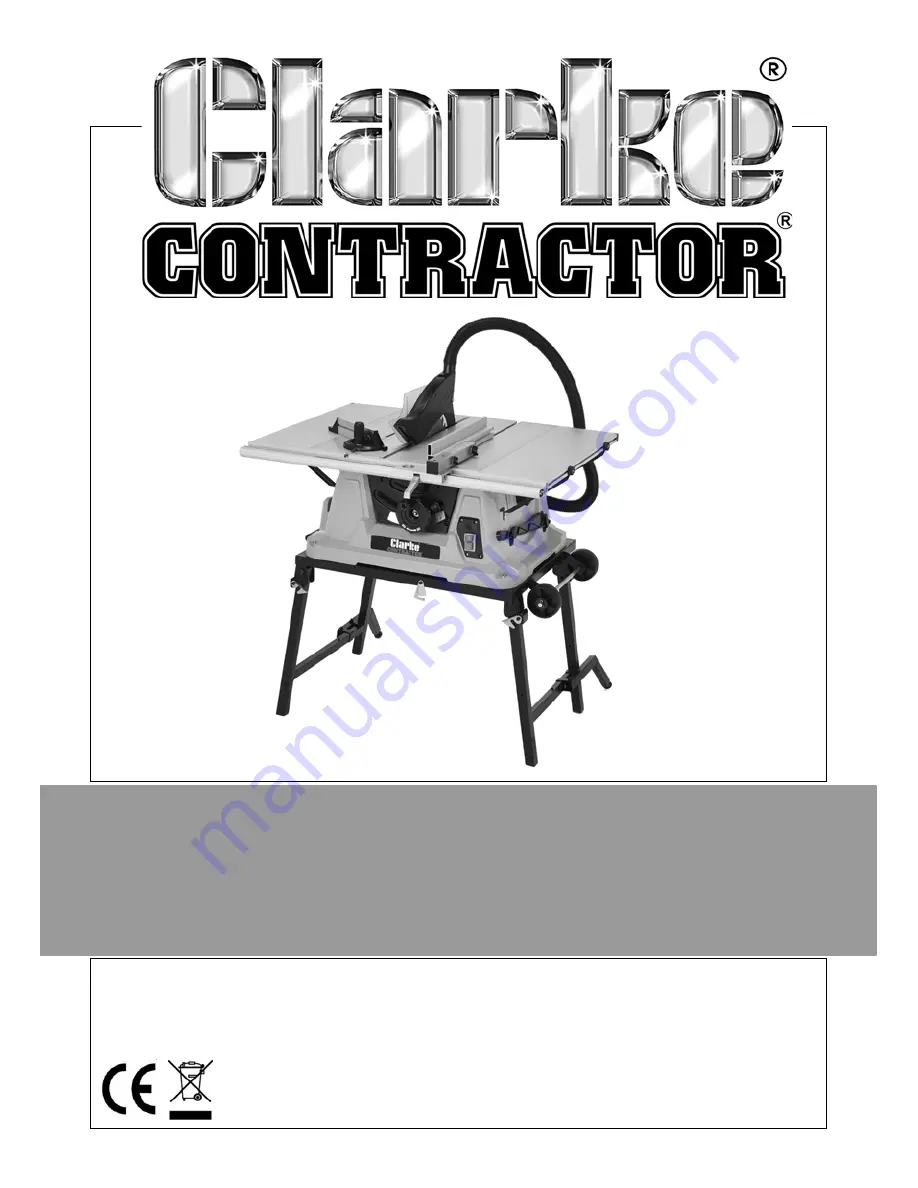
10” TABLE SAW WITH LASER & STAND
MODEL NO: CTS13L
PART NO: 6500820
Page 1: ...OPERATION MAINTENANCE INSTRUCTIONS LS0913 10 TABLE SAW WITH LASER STAND MODEL NO CTS13L PART NO 6500820...
Page 2: ...se Please keep your receipt which will be required as proof of purchase This guarantee is invalid if the product is found to have been abused or tampered with in any way or not used for the purpose fo...
Page 3: ...roscopic particles GENERAL 1 Do not expose the tool to rain 2 Do not use the tool in damp or wet conditions 3 Keep the work area well lit 4 Do not use the tool in the presence of flammable liquids and...
Page 4: ...fore use inspect the extension cable and replace if damaged When using the tool outdoors only use extension cables intended for outdoor use and marked accordingly 22 Avoid unintentional starting Make...
Page 5: ...sons using original spare parts otherwise this may result in considerable danger to the user 40 Keep handles dry clean and free from oil and grease 41 Unplug the tool Switch off and wait for the blade...
Page 6: ...to a complete stop Before using the tool on an actual workpiece let it run for a while Watch for vibration or wobbling that could indicate poor installation or a poorly balanced blade Always hold work...
Page 7: ...You can avoid kickbacks by a keeping the blade sharp b keeping the rip fence parallel to the blade c keeping the riving knife and blade guard in place and operating properly d by not releasing the wor...
Page 8: ...ervice clarkeinternational com SAFETY SYMBOLS LASER SAFETY Read this instruction booklet carefully before positioning operating or adjusting the table saw Wear eye protection Wear ear protection Wear...
Page 9: ...oured black The BROWN wire must be connected to the terminal which is marked L or coloured red The YELLOW AND GREEN wire must be connected to the terminal which is marked E or or coloured green We str...
Page 10: ...keinternational com PART IDENTIFICATION 1 Extractor Hose 9 Blade Bevel Handle 2 Blade Guard 10 Lock Lever 3 Riving Knife 11 Parallel Fence 4 Extension Table 12 Mitre Gauge 5 Handle 13 Stand Locking La...
Page 11: ...ly to the stand using the 4 hexagon bolts as shown The wheels should be attached to the opposite side to the handle FITTING THE EXTRACTOR ADAPTOR 1 Fasten the extractor adapter with the 4 screws to th...
Page 12: ...her and nut as shown 3 Fit the hose bracket using the other 2 coach bolts NOTE The right extension table is now ready to be installed 4 Slide a coach bolt into the left extension table fit a joining b...
Page 13: ...a washer and nut tighten the nut just enough to hold the extension table in place 10 Repeat steps 6 8 with the left extension table FITTING THE EXTENSION TABLE SUPPORTS 11 Insert the four locking pla...
Page 14: ...aw using the bolts supplied NOTE you may need to slide the fixed end of the support arm in a little to line up correctly 18 Tighten up all the bolts Make sure that the table is firm and fully secure b...
Page 15: ...NOTE Take care as the lower set of legs may fall towards you 3 Secure the legs in place using the latches at the top of the legs 4 Lift the table saw allowing the remaining set of legs to swing under...
Page 16: ...ts maximum setting 2 Remove the countersunk screws and lift the table insert away from the table saw 3 Slacken the fixing screw and slide the riving knife behind the bracket as shown 4 Lightly tighten...
Page 17: ...blade off the inner flange by dropping the blade at an angle 5 Clean the blade mounting flange thoroughly before fitting the new blade 6 Mount and fasten the new blade in reverse order IMPORTANT Note...
Page 18: ...ust be able to rise and fall freely 3 Attach the extractor hose to the extractor socket of the blade guard 4 To remove the saw blade guard proceed in reverse order The guard must always be lowered ove...
Page 19: ...AA batteries taking care to follow the polarity diagram inside the compartment 4 Replace the battery cover and screws TURNING ON OFF 1 Press I on the on off switch to turn the laser on 2 Press O on th...
Page 20: ...one to the other you have to 1 Loosen the two knurled screws 2 Remove the parallel fence from the holder 3 Remount the parallel fence on the holder by sliding the holder into the relevant mounting sl...
Page 21: ...ise 3 Rotate the fence until the arrow points to the angle you want 4 Retighten the handle CUTTING DEPTH Turn the hand crank to set the blade to the required cutting depth Turn anti clockwise larger c...
Page 22: ...ur mains supply OPERATION ON OFF SWITCH 1 To turn the saw on press the green button I Wait for the blade to reach its maximum speed before commencing with the cut 2 To turn the machine off again press...
Page 23: ...osition that is in line with the cutting direction 2 Set the parallel fence in accordance with the workpiece height and the desired width 3 Switch on the saw 4 Place your hands with fingers closed fla...
Page 24: ...t in use place the push stick in its storage clip on the side of the saw Replace a worn or damaged push stick immediately BEVEL CUTS Bevel cuts must always be made using the parallel fence 1 Undo the...
Page 25: ...vents your hand and the mitre gauge from making contact with the blade guard 4 Press the workpiece firmly against the mitre gauge 5 Switch on the saw 6 Push the mitre gauge and the workpiece toward th...
Page 26: ...secure using the latch shown below 3 Starting with the leg on the right of the machine support the table saw buy holding the extension table then rotate the locking plate to release the leg 4 Fold the...
Page 27: ...rint We reserve the right to change specifications at any time without prior notice WARNING REMOVE THE PLUG FROM THE MAINS POWER SUPPLY BEFORE CARRYING OUT ANY ADJUSTMENT SERVICING OR MAINTENANCE Volt...
Page 28: ...28 Parts Service 020 8988 7400 E mail Parts clarkeinternational com or Service clarkeinternational com EXPLODED DIAGRAM...
Page 29: ...29 Parts Service 020 8988 7400 E mail Parts clarkeinternational com or Service clarkeinternational com EXPLODED DIAGRAM...
Page 30: ...gle Indicator DDTJ250Q03010 1044 Push Stick DDTJ315B06012A 1045 Wrench DDTJ250B06020 1048 Switch Box DDTJ250Q04003 1050 Blade Bracket DDTJ250Q04005 1051 Blade Flanges DDRTS250H03012 1071 Switch DDKJD2...
Page 31: ...31 Parts Service 020 8988 7400 E mail Parts clarkeinternational com or Service clarkeinternational com DECLARATION OF CONFORMITY...
Page 32: ......