background image

7

3.

To start the compressor pull UP the ON/OFF knob to the ‘ON’ (I) position - the
motor should start immediately.

Note: Should the motor fail to start immediately, it is probable that the air receiver
is already full of air. Check the tank pressure gauge (see fig. 2).  If you release air,
by opening air outlet tap, the motor will start automatically once the cut-in pressure
is reached.

4.

Before connecting your airline to the compressor allow it to run with the air
outlet tap completely open for 10 to 15 seconds to permit a good distribution
of the lubricating oil.

5.

Close the outlet tap then connect one end of suitable air hose to the
compressor air outlet, and the other and to the equipment to be used.

Set the outlet pressure by adjusting the Output Pressure Regulator. To do this,
turn the knob clockwise to increase pressure, anti-clockwise to decrease.

Align your desired pressure setting, shown on the top of the regulator knob,
with the arrow on the casing.

Note: For most spraywork do not exceed 50 psi (unless following paint manuf-
acturer’s instructions).

For other airline equipment such as air tools, tyre gauges, staple guns, paraffin
guns etc., it may be necessary to set the operating pressure at a higher (or lower)
level.

IMPORTANT:

 Always refer to the accessory manufacturers’ recommendations

for optimum operating pressures for their equipment.

6.

With operating pressure set, reopen the air outlet tap.

7.

The Pressure Switch, located within the plastic cover beneath the ON/OFF
knob,  should not require adjustment. This is an automatic device and has
been preset at the factory to stop the motor when pressure in the receiver
reaches its maximum, and to start it again when the pressure falls to the
minimum preset value. This operation is completely automatic and does not
affect the spraying process in any way. However, should problems develop
with the cut-in, cut out settings, consult your local Clarke dealer.

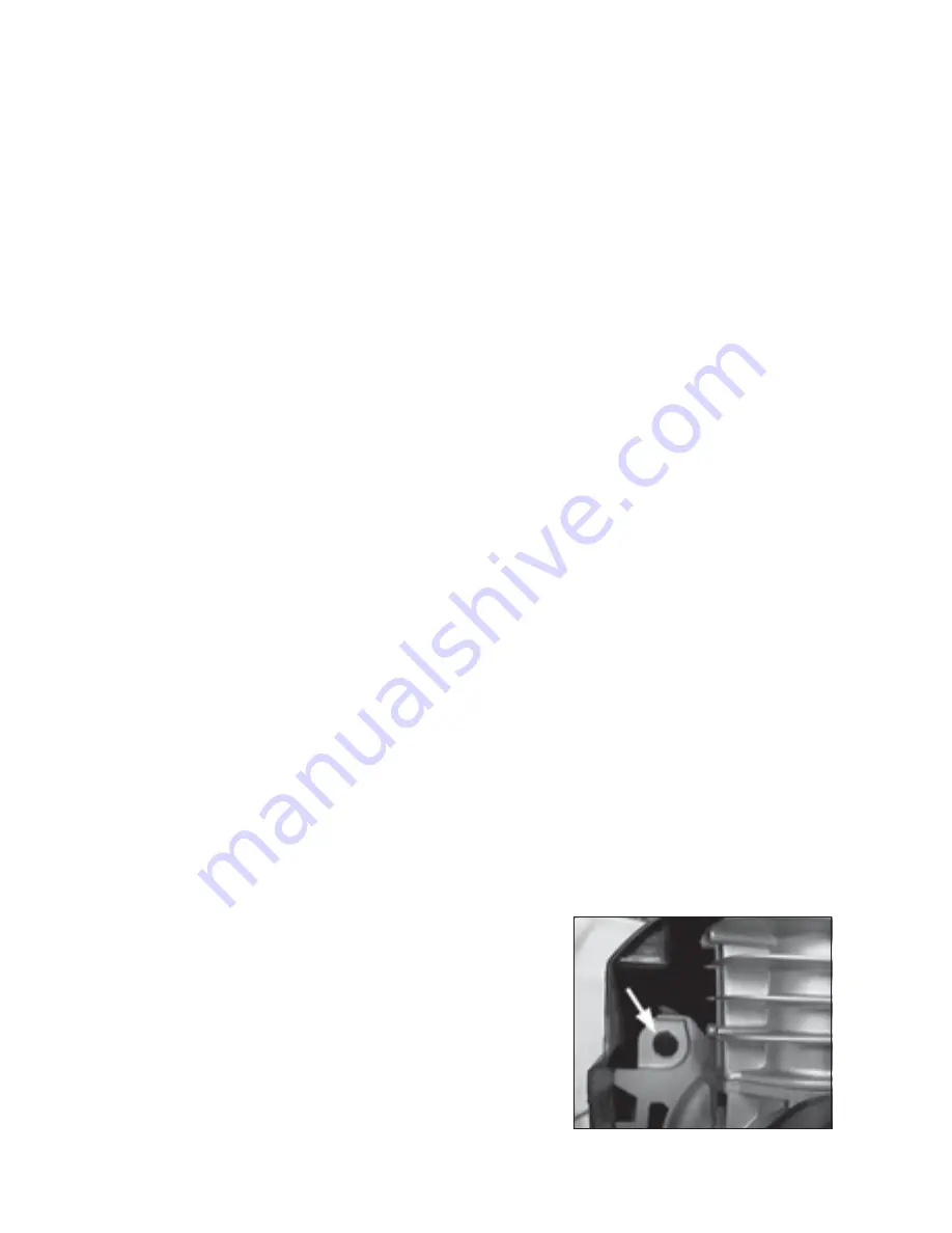
Fig. 3

Note:
a.

If the machine pumps continuously
 without cutting out then the compressor is
too small for the application/tool being used,
and damage may result. Consult your local
Clarke dealer.

b.

The motor is protected by a Thermal Overload
so that if the motor  overheats for any reason
-the thermal overload will trip, stopping the
motor. To restart, allow a period for the motor
to cool down, (approx 5 mins), before
pressing the Reset Button, arrowed in fig. 3.
and shown at ‘C’, fig.6

Summary of Contents for COUGAR 25

Page 1: ...0903 COUGAR OPERATING MAINTENANCE INSTRUCTIONS COUGAR...

Page 2: ...y service GUARANTEE This product is guaranteed against faulty manufacture for a period of 12 months from the date of purchase Please keep your receipt as proof of purchase This guarantee is invalid if...

Page 3: ...l parts can become quite hot during operation Take care not to touch these until the machine has cooled down 9 Always adjust the pressure regulator to the recommended setting for the particular spray...

Page 4: ...ed with a plug which is moulded onto the electric cable i e non rewireable please note 1 The plug must be thrown away if it is cut from the electric cable There is a danger of electric shock if it is...

Page 5: ...E40 Compressor Oil Available from your local Clarke dealer 3 Attach the wheels foot and handle according to the instructions shown on the polythene bag containing the items Cougar 25 only OPERATION NO...

Page 6: ...ir tools tyre gauges staple guns paraffin guns etc it may be necessary to set the operating pressure at a higher or lower level IMPORTANT Always refer to the accessory manufacturers recommendations fo...

Page 7: ...art and top up if necessary use Clarke SAE 40 compressor oil available from your local dealer 2 Drain any condensate that may have accumulated in the receiver by unscrewing the drain plug beneath the...

Page 8: ...hours of operation or every 6 months clean all the external parts of the compressor This cleaning makes the cooling process more efficient and prolongs the life of the machine Examine the non return...

Page 9: ...nearest dealer NOTE It is also possible that you are using more air than the compressor is capable of delivering Compressor does not start Air receiver charged see also item 1 Open drain cock to expel...

Page 10: ...st dealer 11 Please note that the details and specifications contained herein are correct at the time of going to print However CLARKE International reserve the right to change specifications at any t...

Page 11: ...FN047113001 13 Valve Assembly compl FN347043000 14 Tube FN046001000 15 Connector FN199110140 No Description Part No 16 Pressure Gauge FN330004000 17 Adapter FN011017000 18 Pressure Regulator FN3190440...

Page 12: ...4000 9 Valve FN347043000 10 Spring FN047113002 11 Washer FN010041000 12 Hand Grip FN020121000 No Description Qty Part No 13 Tube FN046001000 14 Connector FN199110140 15 Pressure Gauge FN330004000 16 A...

Page 13: ...14 COMPRESSOR...

Page 14: ...N116121012 16 Gasket 1 FN116120013 17 Valve Block Assy 1 FN116120100 18 Gasket 1 FN116120014 19 Cyl Head Screw M6 2 FN014013031 No Description Qty Part No COMPRESSOR 20 Cylinder Head 1 FN116120015 21...

Reviews: