background image

14

Parts & Service: 020 8988 7400 / E-mail: [email protected] or [email protected]

• The direction of the cutting motion is important. Always feed the 

cutting disc into the work so that it cuts in an upward direction. If you 
do not do this It can result in the disc climbing out of the cut in an 
uncontrolled manner and may lead to loss of control or serious injury.

• Whenever a new disc has been fitted, always run the grinder at no 

load speed to check for irregularities before starting work.

GRINDING TIPS

• The key to efficient grinding is to control the pressure and surface 

contact between the grinding disc and the workpiece.

• Flat surfaces are ground at an acute angle, usually 15 to 30 degrees 

to the workpiece. Too great an angle causes concentration of 
pressure on a small area which may gouge, or burn the workpiece.

• Allow the disc to reach full speed before grinding.

• Avoid overloading the angle grinder. If it becomes hot when being 

used, allow it to run for a few minutes under no-load conditions.

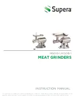
SELECTING THE CORRECT GUARD

A open and a closed guard is 
supplied with the CON1050B.

The “open” guard is for grinding and 
the “closed” one is for cutting.

The open guard should be used with 
type 27, 28 and 29 discs as follows;

• Type 27 - Depressed centre 

grinding wheels

• Type 28 - Depressed centre 

grinding wheels cone shaped

• Type 29 - Depressed centre semi-flexible wheels

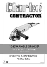
The closed guard should be used with type 1, 41 & 42 discs as follows;

• Type 1 - Straight grinding wheels

• Type 41 - Flat cutting off wheels

• Type 42 - Depressed centre cutting off wheels.

WARNING: WHEN GRINDING, ONLY USE DISCS SPECIFICALLY DESIGNED 
FOR GRINDING. YOU MUST NEVER USE CUTTING DISCS TO GRIND ANY 
MATERIAL.

Summary of Contents for CONTRACTOR CON1050B

Page 1: ...OPERATING MAINTENANCE INSTRUCTIONS GC1014 1050W ANGLE GRINDER MODEL NO CON1050B PART NO 6474010...

Page 2: ...iod of 12 months from the date of purchase Please keep your receipt which will be required as proof of purchase This guarantee is invalid if the product is found to have been abused or tampered with i...

Page 3: ...international com or Service clarkeinternational com SAFETY SYMBOLS The following safety symbols may be found on the machine Wear ear protection Wear eye protection Falls within WEEE Directive Read in...

Page 4: ...the plug in any way Do not use adapter plugs with earthed grounded power tools Unmodified plugs and matching outlets will reduce the risk of electric shock 2 Do not expose power tools to rain or wet c...

Page 5: ...ry or long hair can be caught in moving parts Keep the work area clean and tidy 7 This tool vibrates with use Vibration may be harmful to your hands or arms Stop using the tool if discomfort a tinglin...

Page 6: ...for purposes not intended 4 Always position the power cable clear of the spinning disc If you loose control the cable may be cut or snagged and you hand drawn onto the spinning disc 5 Start up speed...

Page 7: ...before putting the angle grinder down 17 Use the disc guard Do not use the angle grinder without the disc guard Make sure that the guard is securely fitted and positioned for maximum safety before op...

Page 8: ...ays use the correct disc for it s intended task Using the incorrect disc can cause serious injury 7 Using the disc Allow the disc and tool to do the work Never force the disc onto the workpiece as thi...

Page 9: ...n into a mains socket could cause an electrical hazard If the colours of the wires in the power cable of this product do not correspond with the markings on the terminals of your plug proceed as follo...

Page 10: ...reported to your CLARKE dealer where the appliance was originally purchased This CON1050B is supplied with the following loose components 2 x Disc Guards 1 x Grinding Disc 1 x Pin Spanner 1 x Side Ha...

Page 11: ...the spindle by hand to fully engage the spindle lock 2 Use the pin spanner supplied to remove the outer flange 3 Ensure the inner flange is fitted correctly with the raised circular section pointing o...

Page 12: ...is pointing towards the disc 5 Screw on the outer flange with the centre boss facing inwards so as to sit inside the aperture of the disc Tighten securely with the pin spanner When using thin discs t...

Page 13: ...SE SERIOUS INJURY WARNING WHEN USING CUTTING DISCS DO NOT STAND DIRECTLY IN LINE WITH THE ROTATING DISC WARNING DO NOT PUT SIDEWAYS PRESSURE ON CUTTING DISCS WARNING ENSURE THAT THE WORKING POSITION A...

Page 14: ...an angle causes concentration of pressure on a small area which may gouge or burn the workpiece Allow the disc to reach full speed before grinding Avoid overloading the angle grinder If it becomes hot...

Page 15: ...ure the grinding wheel or cutting disc is perfectly sound free from cracks or damage 6 Inspect the power cable to ensure it is sound and free from cracks or bare wires etc CLEANING To maintain the bes...

Page 16: ...PECIFICATIONS Model Number CON1050B Dimensions L x W x H 362 x 137 x 105 mm Weight 2 3 kg Input Power 1050 W Disc Diameter 115 mm Disc Bore 22 mm Spindle Thread Size M14 No Load Speed 11 500 rpm Sound...

Page 17: ...17 Parts Service 020 8988 7400 E mail Parts clarkeinternational com or Service clarkeinternational com PARTS LIST DIAGRAM...

Page 18: ...ew 8 Flat Washer 35 Motor Stator 9 Spindle 36 Motor Bearing 10 Spindle Housing 37 Motor Housing 11 Bearing 38 Brush Holder 12 Bearing Platten 39 Screw 13 Screw 40 Carbon Brush 14 Drive Gear 41 Disc Gu...

Page 19: ...19 Parts Service 020 8988 7400 E mail Parts clarkeinternational com or Service clarkeinternational com DECLARATION OF CONFORMITY...

Page 20: ......

Reviews: