

9
Parts & Service: 020 8988 7400 / E-mail: [email protected] or [email protected]
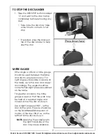
TO STOP THE DISC SANDER
1. Press the RED STOP button marked
‘O’ and wait for the disc to stop
completely before removing any
dust.
• Take care, the disc may take
some time to come to a full
stop.
• If required, press the brake on
top of the disc sander to help
slow the disc.
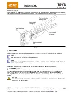
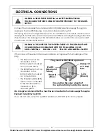
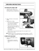
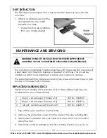
MITRE GAUGE
If the angle is critical, a mitre gauge
should be used between the table
and disc to ensure accuracy. For
right angles, simply slide a square on
the table, up to the disc, and adjust
accordingly. The angle should be
correct when slight pressure is placed
on the table.
For greater accuracy, the mitre
gauge is used so that the work may
be held at a required angle and
moved across the disc as shown.
Use a slight pressure ONLY... let the
disc do the work. Pressure should be
on the DOWNWARDS direction of
motion of the disc ONLY. i.e. on the
left half of the disc as shown.
NOTE:
Applying the workpiece to
the right hand side of the
disc may cause kickback.