background image

8

Parts & Service: 020 8988 7400 / E-mail: [email protected] or [email protected]

OPERATING INSTRUCTIONS

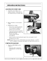
ADJUSTING THE WORK TABLE

1. Adjust the work table to the 

desired angle by slackening the 
two table clamps, one either side, 

2. Move the table to the required 

angle.

3. Retighten the clamps.

• The clamps are spring loaded. 

Turn the lever clockwise to 
clamp, as far as possible.

• Then pull the lever out against 

spring pressure which allows the 
lever to be turned 
anticlockwise without 
unclamping. 

• Allow the lever to spring inwards again, then proceed to turn it 

clockwise once more.

NOTE: 

Repeat the process until the table is securely clamped.....but DO 

NOT overtighten, otherwise damage to the mechanism will occur.

STARTING THE MACHINE

1. Press the GREEN START button 

marked ‘I’. 

• Allow the disc to reach full 

speed before commencing 
work.

Summary of Contents for CDS300B

Page 1: ...OPERATION MAINTENANCE INSTRUCTIONS LS1113 12 DISC SANDER MODEL NO CDS300B PART NO 6500411 ...

Page 2: ...on This guarantee does not effect your statutory rights FEATURES This 305 mm disc sander is ideal for finish fitting altering bevel angles sanding convex curves to the line and sanding end grain without burning etc The machine is provided with a work table which is capable of tilting to 45 degrees and a mitre gauge in which the work may be held and which moves in a mitre gauge slot parallel to the...

Page 3: ...circular saws to cut tree limbs or logs 8 Dress properly Do not wear loose clothing or jewellery they can be caught in moving parts Non skid footwear is recommended when working outdoors Wear protective hair covering to contain long hair 9 Use protective equipment Use safety glasses Use face or dust mask if working operations create dust 10 Connect dust extraction equipment If the tool is provided...

Page 4: ...ou are doing use common sense and do not operate the tool when you are tired 20 Check damaged parts Before further use of tool it should be carefully checked to determine that it will operate properly and perform its intended function Check for alignment of moving parts binding of moving parts breakage of parts mounting and any other conditions that may affect its operation A guard or other part t...

Page 5: ... ALWAYS make sure there are no nails or foreign objects in the part of the workpiece to be sanded ALWAYS set up the machine and make all adjustments with the power OFF and disconnected from the supply ALWAYS use the correct type and size of sanding disc for each operation ALWAYS maintain a gap of 1 5 2mm MAX between the sanding Disc and the table ALWAYS take great care if sanding non ferrous metal...

Page 6: ... connected to the terminal which is marked N or coloured black The BROWN wire must be connected to the terminal which is marked L or coloured red The YELLOW AND GREEN wire must be connected to the terminal which is marked E or or coloured green We strongly recommend that this machine is connected to the mains supply through a Residual Current Device RCD If you are not sure consult a qualified elec...

Page 7: ... transit Should any damage be apparent contact your Clarke dealer immediately Your disc sander is fully assembled except for the dust extraction and the mitre gauge POSITIONING THE SANDER Install the machine on a solid base one that will not move easily Ensure that the machine is horizontal and perfectly stable Alternatively the rubber feet may be removed and the machine bolted directly to a solid...

Page 8: ... are spring loaded Turn the lever clockwise to clamp as far as possible Then pull the lever out against spring pressure which allows the lever to be turned anticlockwise without unclamping Allow the lever to spring inwards again then proceed to turn it clockwise once more NOTE Repeat the process until the table is securely clamped but DO NOT overtighten otherwise damage to the mechanism will occur...

Page 9: ...re gauge should be used between the table and disc to ensure accuracy For right angles simply slide a square on the table up to the disc and adjust accordingly The angle should be correct when slight pressure is placed on the table For greater accuracy the mitre gauge is used so that the work may be held at a required angle and moved across the disc as shown Use a slight pressure ONLY let the disc...

Page 10: ...e panel beneath the table is secured by two screws Remove these to gain access to the lower half of the disc REPLACING SANDING DISCS Replacement sanding discs packets of 5 in three different grit sizes are available from your Clarke dealer 1 Peel off the worn disc from the machine 2 Remove the protective cover from the back of the new sanding disc 3 Gently slide it between the work table and disc ...

Page 11: ...RMITY Motor 230V 50Hz 1Ph Speed 1490 RPM Power Rating On load 900 Watts Fuse Rating 13 Amps Disc Size 305 mm Dimensions Overall 440 x 437 x 386 Table Size 437 x 153mm Table Tilt 0 45O Down Mitre Gauge 0 60O Both directions Dust Extraction Outlet ID 46 mm Dust Extraction Outlet OD 51 mm Weight unpacked 28 kg Noise Level no load 93 4 dB A ...

Page 12: ......

Reviews: