WARNING:
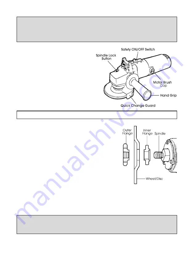
NEVER press the spindle lock button when starting the tool, and
NEVER press the button when the tool is operating.
DO NOT press button until the wheel/disc has stopped completely
3.
Quick Change Guard.
The guard is capable of rotating about
its axis. Grasp it firmly and turn to the
desired position
before
connecting the
tool to the mains supply and switching
ON.
You should always turn the guard so as
to provide the greatest amount of
protection for the hand gripping the
hand grip, without impeding the work
being carried out.
ASSEMBLY
1.
Mounting the Grinding Wheel/Cutting Disc.
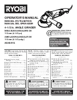
1.1 Unscrew and remove the outer flange. If it
is tight, lock the spindle by pressing the
Spindle Lock button and use the tool
supplied to turn the flange to break the
seal. It may then be screwed off by hand.
1.2 The Grinding wheel supplied is a Depressed
Centre’ type. Mount it as shown in the
diagram. i.e. with the depressed centre
towards the motor,
1.3 Ensuring the wheel sits snugly over the
raised boss on the inner flange, screw on
the outer flange with the centre boss facing inwards.
Tighten the flange using the tool provided, locking the spindle by pressing
the Spindle Lock button, and taking care to ensure the wheel is still sitting
snugly, centred over the flange bosses. Care should be taken also NOT to
overtighten the outer flange.
IMPORTANT:
Fig . 2 shows the set up for a grinding wheel.
When attaching a cutting disk, YOU MUST REVERSE the Outer flange.
2.
Hand Grip
A threaded hole, on the left or right hand side of the gear housing, is provided so
that the hand grip may be screwed in, as required, to provide left or right hand
control of the tool.
6
Fig 1.
Fig 2.


