background image

15

Parts & Service: 020 8988 7400 / E-mail: [email protected] or [email protected]

2. Stand to the side of the stone and hold the dresser handle firmly. Place the 

dresser on the tool support so that its wheels can move freely (i.e, the 
exposed part of the wheel should be facing up). Run the stone and apply 
the dresser to the surface of the stone.

3. When the abrasive wheel starts to become clogged with debris, use the 

dresser tool supplied to clean (dress) it

CHANGING THE SANDING BELT

To renew or change the sanding belt proceed as follows:

1. Unplug from the power supply. 

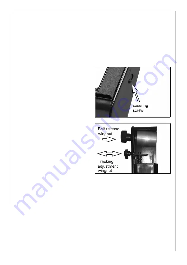
Remove the sander side cover by 
unscrewing the securing screw.

2. Slacken the top roller securing 

wingnut, allowing the top roller to 
move slightly off its axis as shown.

3. Slide the belt off and replace with 

a new one, ensuring it lies 
centrally on the top and bottom 
rollers

4. Retighten the top roller securing 

wingnut till it becomes firm but 
NOT too tight. The belt should now 
be fairly taught and positioned 
centrally on the rollers.

IMPORTANT: The belt needs just 
enough tension to ensure that it does 
not slip on the rollers whilst under 
load, however too much tension will 
shorten the working life of the belt 
and the machine.

5. Replace the sanding belt cover.

6. Rotate the belt by hand whilst screwing the Tracking Adjustment screw in or 

out to ensure the belt runs centrally on the rollers. Turn the screw 
anticlockwise to move the belt outwards (towards the outer cover), or 
clockwise to move inwards.

7. When satisfied, plug the machine into the power supply and switch on. 

Make fine adjustments with the Tracking Adjustment screw if necessary.

CLEANING & STORAGE

Clean the exterior of the machine if required using a mild detergent or mild 
solvent. NEVER immerse the machine in water. To reduce any fire hazard, keep 

Summary of Contents for 6502130

Page 1: ...OPERATING MAINTENANCE INSTRUCTIONS ORIGINAL INSTRUCTIONS GC08 22 BENCH GRINDER WITH SANDING BELT MODEL NO CBG6SC PART NO 6502130...

Page 2: ...or not used for the purpose for which it was intended Faulty goods should be returned to their place of purchase no product can be returned to us without prior permission This guarantee does not effec...

Page 3: ...that have the switch on invites accidents 3 DO NOT overreach Keep proper footing and balance at all times This enables better control of the power tool in unexpected situations 4 Dress properly DO NOT...

Page 4: ...s of untrained users 12 Maintain power tools Check for misalignment or binding of moving parts breakage of parts and any other condition that may affect the power tools operation If damaged have the p...

Page 5: ...essories must be within the capacity rating of the power tool The correct size accessories can be correctly guarded and controlled 3 NEVER use a stone that is chipped cracked or damaged Fragments from...

Page 6: ...if any damage is found 5 ALWAYS use the tool rests to steady the workpiece the torque of the spinning grinding wheel may pull the workpiece from your hands 6 ALWAYS check for damaged parts Before furt...

Page 7: ...ns shown below The old plug must be disposed of safely as insertion into a mains socket could cause an electrical hazard If the colours of the wires in the power cable of this product do not correspon...

Page 8: ...Description 1 Eye Shield 9 Dust Extract Port 2 Flexible Lamp 10 Dust Collector Belt guard 3 Grinding Wheel Dresser 11 Mounting Bolt Location 4 Belt Tracking Adjustment Knob 12 On Off Switch 5 Belt Te...

Page 9: ...UNTING THE MACHINE ON A WORKBENCH NOTE We highly recommend that you bolt this machine securely to a workbench to gain maximum stability 1 Using the base of the machine as a template mark and drill the...

Page 10: ...wheel guard using the screw and washers provided FITTING THE EYESHIELD Fit the eyeshield to the grinding wheel guard using the clamp bolt and washers provided FITTING THE SANDING WORK REST Fit the wor...

Page 11: ...easily be positioned by hand 3 Check the grinding wheel guard and make any adjustments necessary before use SETTING THE TOOLREST 1 Slacken the tool rest securing knob and position the rest so that it...

Page 12: ...eater than the thickness of the metal being ground there is a danger that the force of grinding will cause the work piece to be pulled into the gap and is potentially dangerous An incorrect gap could...

Page 13: ...omponents are tight and secure ALWAYS have any damaged or worn parts repaired or replaced by qualified service personnel DO NOT attempt to repair the bench grinder unless you are qualified to do so Th...

Page 14: ...n the wheel retaining nut 4 Refit the grinding wheel cover and re adjust the tool rest and spark arrester brackets to suit the new wheel 5 Switch the machine on and allow it to rotate freely for at le...

Page 15: ...one ensuring it lies centrally on the top and bottom rollers 4 Retighten the top roller securing wingnut till it becomes firm but NOT too tight The belt should now be fairly taught and positioned cen...

Page 16: ...02120 Sanding Belts Coarse pack of 5 6502125 Bench Grinder Stand CBGS2 6501142 Problem Possible Cause Action Motor doesn t start a ON OFF switch damaged b Switch cable damaged c ON Off relay damaged d...

Page 17: ...17 Parts Service 020 8988 7400 E mail Parts clarkeinternational com or Service clarkeinternational com COMPONENT PARTS...

Page 18: ...Nut 10 Nut 40 Screw 11 Screw 41 Capacitor 12 Eyeshield Support Bracket 42 Capacitor Bracket 13 Washer 43 Cable Clamp 14 Flat Washer 44 Screw 15 Bolt 45 Plastic Base Plate 16 Nut 46 Cable Gland 17 Cla...

Page 19: ...r 79 Retaining Nut 67 Screw 80 Screw 68 Belt Support Platen 81 Spring washer 69 Large Tensioning Wingnut 82 Flat Washer 70 Flat Washer 83 Extract Duct 71 Spacer 84 Cap Nut 72 Spring 85 Screw 73 Tracki...

Page 20: ...20 Parts Service 020 8988 7400 E mail Parts clarkeinternational com or Service clarkeinternational com DECLARATION OF CONFORMITY UK...

Page 21: ...21 Parts Service 020 8988 7400 E mail Parts clarkeinternational com or Service clarkeinternational com DECLARATION OF CONFORMITY CE...

Page 22: ...22 Parts Service 020 8988 7400 E mail Parts clarkeinternational com or Service clarkeinternational com USEFUL CLARKE PRODUCTS...

Page 23: ...23 Parts Service 020 8988 7400 E mail Parts clarkeinternational com or Service clarkeinternational com USEFUL CLARKE PRODUCTS...

Page 24: ......

Reviews: