Clarke 6501661 Operation & Maintenance Instructions Manual Download Page 13

13

Parts & Service: 020 8988 7400 / E-mail: [email protected] or [email protected]

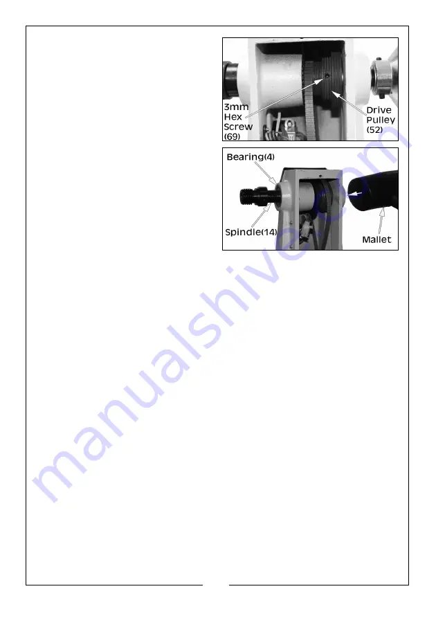
3. Loosen the 3mm hex screw (69) 

on the drive pulley (52).

4. Tap out the spindle (14) using a 

mallet.

NOTE: 

If you don’t have a mallet, 

place a block of wood 
against the spindle and tap 
with a hammer.

5. To get the spindle completely out, 

use a flat head screwdriver to tap 
it the rest of the way.

NOTE: 

Be careful not to damage the bearings or the threads.

6. Replace the bearings, spindle or belt as required.

BELT: 

You need only to move the spindle enough to slide a new belt on.

SPINDLE: 

You must knock the spindle completely out through both bearings.

BEARINGS: 

After removal of the spindle, completely knock out the bearings 

from the inside of the headstock. This is best accomplished by inserting a 
long rod or screwdriver through one bearing inside the headstock toward 
the opposite bearing. tap firmly to remove the bearing from the casting. Do 
the same for the second bearing. Please be aware not to damage the 
retainer rings (13) when tapping out the bearing. Reassemble the new bear-
ings by tapping them into place from the outside and replace spindle.

NOTE: 

You may have to loosen the motor plate screws (44, 45 & 46) to 

reinstall the drive pulley (52), spindle collar (3) and belt (53).

7. Reinstall the hand wheel (1) and 3mm hex set screws (2).

NOTE: DO NOT

 tighten the hand wheel against the bearings

8. Tighten the pulley 3mm hex screw (69) and close the rear belt door (7)

Please refer to TROUBLESHOOTING on page 17. If you are unable to rectify any 
faults, please contact your local dealer or CLARKE International Service 
Department on 0208 988 7400 for assistance.

Summary of Contents for 6501661

Page 1: ...OPERATION MAINTENANCE INSTRUCTIONS ORIGINAL INSTRUCTIONS GC0621 18 VARIABLE SPEED WOOD LATHE MODEL NO CWL460 PART NO 6501661...

Page 2: ...f purchase Please keep your receipt as proof of purchase This guarantee is invalid if the product is found to have been abused or tampered with in any way or not used for the purpose for which it was...

Page 3: ...ain for future reference ELECTRICAL SAFETY 1 Power tool plugs must match the outlet NEVER modify the plug in any way DO NOT use adapter plugs with earthed grounded power tools Unmodified plugs and mat...

Page 4: ...and balance at all times This enables better control of the power tool in unexpected situations 6 Keep your hair and clothing away from moving parts Loose clothes jewellery or long hair can be caught...

Page 5: ...with dust 8 Check the power tool for damage before using the machine Any damaged part should be inspected to ensure that it will operate properly and perform its intended function Check for alignment...

Page 6: ...orted and taken to a recycling centre for disposal in a manner which is compatible with the environment ENVIRONMENTAL RECYCLING POLICY Through purchase of this product the customer is taking on the ob...

Page 7: ...The old plug must be disposed of safely as insertion into a mains socket could cause an electrical hazard If the colours of the wires in the power cable of this product do not correspond with the mar...

Page 8: ...ARKE dealer immediately The following components are supplied with the lathe assembly Item Description Item Description 1 Handwheel 10 Tailstock Centre Cup 2 LED Variable Speed Display 11 Tailstock 3...

Page 9: ...ng the rest locking handle and base locking handle 3 Install the headstock faceplate by screwing it onto the headstock spindle using the drift rod as a counter lever Lock the faceplate into place usin...

Page 10: ...the lathe 4 Press the green push button I to start the lathe and adjust the speed using the speed control knob NOTE Always use the lowest speed when starting a new workpiece see Adjusting The Belt Pos...

Page 11: ...access to the drive pulley 3 Loosen the lock screw that is holding the motor plate using the 6mm hex key Allowing the motor plate to swivel upwards 4 Move the belt to the required pulley as shown in t...

Page 12: ...f the mounting bolts 4 Check the drive belt for wear and replace if it is frayed or otherwise damaged 5 Periodically lubricate the tail stock screw threads with engine oil such as SAE20 or SAE30 grade...

Page 13: ...the inside of the headstock This is best accomplished by inserting a long rod or screwdriver through one bearing inside the headstock toward the opposite bearing tap firmly to remove the bearing from...

Page 14: ...14 Parts Service 020 8988 7400 E mail Parts clarkeinternational com or Service clarkeinternational com COMPONENT PARTS DIAGRAM...

Page 15: ...40 Hex Socket Screw M10 x 12 11 Screw 41 Lock Plate 12 Headstock 42 Nut M10 13 Circlip 43 n a 14 Headstock Spindle 44 n a 15 Faceplate 45 n a 16 Headstock Spur Centre 46 Lock Screw 17 Locking Handle 4...

Page 16: ...76 Cover 67 Variable Speed Knob 77 Variable Plate 68 On Off Switch 78 Screw 69 Hex Socket Taper Screw M6 x 12 79 Transformer 70 Motor Wood Turning Chisel Set CHT874 4 Sided Diamond Sharpener CHT593 SA...

Page 17: ...e circuit Check the power supply for correct voltage Use another circuit or have a qualified electrician upgrade the power supply Motor will not start and fuses or circuit breaker trip out 1 Short cir...

Page 18: ...18 Parts Service 020 8988 7400 E mail Parts clarkeinternational com or Service clarkeinternational com DECLARATION OF CONFORMITY...

Page 19: ...19 Parts Service 020 8988 7400 E mail Parts clarkeinternational com or Service clarkeinternational com DECLARATION OF CONFORMITY...

Page 20: ......

Reviews: