background image

o

11

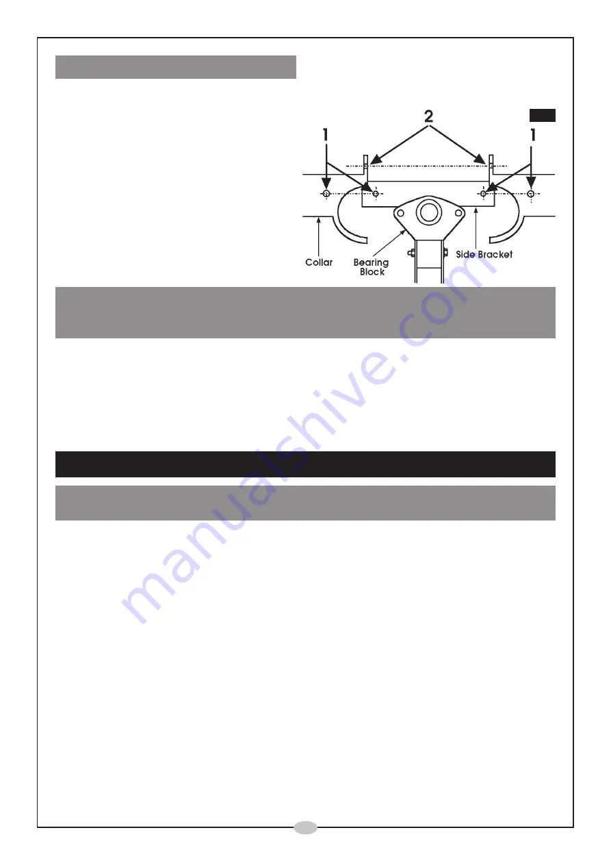
9. Fitting the Drum Collar

Before the collar is attached, it is strongly recommended that a layer of grease (not supplied)
be applied to the underside of the serrated rim of the lower drum.

9.1 Secure each half of the collar to the

side brackets first. (Shown at ‘1’, Fig.
12). Use a single M6 x 10mm  bolt with
a flat and spring washer.

9.2  Bolt the two halves together using two

M6 x 20mm bolts with a flat washer,
spring washer and nut, shown at ‘2’
Fig.. 12

Fig.12

IMPORTANT:
The Drum Collar is a Safety Feature, and must ALWAYS be in place. NEVER operate the
machine with the collar removed.

Congratulations......your Concrete Mixer is now fully assembled and ready for use.

Please consult the engine manufacturers handbook, enclosed, for full details as to how to

start, operate and maintain your engine.

OPERATION

IMPORTANT:

ALWAYS start the engine and have the drum rotating, BEFORE loading the drum.

To start the engine please refer to the manufacturers handbook which accompanies this
manual.

In addition to the precautions laid out in the engine manual, ensure the throttle is set to fully
open, i.e. against the stop, before pulling the recoil starter. In this position, the engine is set to
run at an ideal speed for drum rotation.

NOTE:

 If the choke is used to start the engine, it is advised that you allow the engine to warm

up sufficient for the choke to be disengaged, before loading the drum.

Once the engine is running smoothly, and the drum rotating, proceed to load the drum with
sand/cement, ensuring the drum is inclined upwards (approx. 30 degrees minimum), to avoid
having the mix thrown out.

In order to rotate the drum, push the Hand Wheel inwards at the rim to disengage the wheel
from the Locking Plate. Turn the drum to the required position then release the handwheel to
lock it in that position.

Summary of Contents for 3400820

Page 1: ...o 1005 Part No 3400820 Model CCM125P CEMENT MIXER CEMENT MIXER OPERATING MAINTENANCE INSTRUCTIONS...

Page 2: ...o 2 Copyright CLARKE International All rights reserved March 2001 Please read this manual in conjunction with the Engine Handbook...

Page 3: ...12 months from the date of purchase Please keep your receipt as proof of purchase This guarantee is invalid if the product is found to have been abused or tampered with in any way or not used for the...

Page 4: ...irs are removed from machine before use NEVER operate the machine whilst under the influence of DRUGS ALCOHOL or any MEDICATION NEVER STAND ON THE MACHINE Injury could occur from a fall NEVER LEAVE MA...

Page 5: ...king case is a 6mm x 305mm steel rod used for pulley alignment and a bag containing all nuts bolts washers and fixings Please refer to the parts list on page 15 for full list 5 A Upper Drum Section B...

Page 6: ...to allow a wheelbarrow to be placed beneath the drum 1 2 Turn the frame over and attach the Leg S in the same manner as shown in Fig 2 1 3 Slide a wheel on to each stub axle followed by a large flat w...

Page 7: ...se that as a pivot by pushing the handwheel IN to square it up in order to line up the holes on the other side When the holes at the opposite side are aligned tap the bolt through GENTLY to avoid dama...

Page 8: ...e rim together with a flat washer and secure from below with a spring washer and nut ensuring the tightening process is carried out progressively 5 4 Secure the Mixing Blades to the Upper Drum by inse...

Page 9: ...ight oil to the engine output shaft then locate the key firmly in the keyway Fig 8 Fig 9 Slide the motor pulley on to the shaft with the grub screw in the centre boss facing inwards towards to engine...

Page 10: ...motor pulley NOTE The gap between the cover and top pulley is small but the operation is possible by rotating the upper pulley whilst easing the belt between the cover and pulley rim 8 3 Slacken off t...

Page 11: ...TION IMPORTANT ALWAYS start the engine and have the drum rotating BEFORE loading the drum To start the engine please refer to the manufacturers handbook which accompanies this manual In addition to th...

Page 12: ...o prevent water from entering the engines electrical components by wrapping a polythene sheet or bag over the engine during the cleaning process Turn the drum so that it is face down to allow all wate...

Page 13: ...evel Guaranteed 94dBLWA Weight 63kg Part Number 3400820 Please contact your nearest dealer or CLARKE International on one of the following numbers PARTS SERVICE TEL 020 8988 7400 PARTS SERVICE FAX 020...

Page 14: ...o PARTS DIAGRAM 14 14...

Page 15: ...nd Cap 1 SD0024 25 Bearing Set 1 SD0025 26 Pinion 1 SD0026 27 Yolk Assy 1 SD0027 28 Bearing Plate Lower 1 SD0028 29 Bearing Set 1 SD0029 30 Bearing Plate Upper 1 SD0030 31 Locking Plate 1 SD0031 32 Ha...

Page 16: ...o...

Reviews: