background image

3

Parts & Service: 020 8988 7400 / E-mail: [email protected] or [email protected]

GENERAL SAFETY RULES

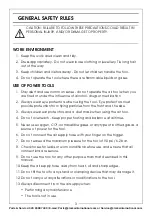
WORK ENVIRONMENT

1. Keep the work area clean and tidy.

2. Dress appropriately - Do not wear loose clothing or jewellery. Tie long hair 

out of the way.

3. Keep children and visitors away - Do not let children handle the tool.

4. Do not operate the tool where there are flammable liquids or gases.

USE OF POWER TOOLS

1. Stay alert and use common sense - do not operate the air tool when you 

are tired or under the influence of alcohol, drugs or medication.

2. Always wear eye protectors when using the tool - Eye protectors must 

provide protection from flying particles from the front and the side.

3. Always wear ear protectors and a dust mask when using the air tool.

4. Do not overreach - Keep proper footing and balance at all times.

5. Never use oxygen, CO

2

, combustible gases or any type of bottled gas as a 

source of power for the tool.

6. Do not connect the air supply hose with your finger on the trigger.

7. Do not exceed the maximum pressure for the tool of 90 psi / 6.2 bar.

8. Check hoses for leaks or worn condition before use, and ensure that all 

connections are secure.

9. Do not use the tool for any other purpose than that described in this 

manual.

10. Keep the air supply hose away from heat, oil and sharp edges.

11. Do not fit the tool to any stand or clamping device that may damage it.

12. Do not carry out any alterations or modifications to the tool.

13. Always disconnect from the air supply when:

• Performing any maintenance.

• The tool is not in use.

CAUTION: FAILURE TO FOLLOW THESE PRECAUTIONS COULD RESULT IN 
PERSONAL INJURY, AND/OR DAMAGE TO PROPERTY.

Summary of Contents for 3120160

Page 1: ...OPERATING MAINTENANCE INSTRUCTIONS ORIGINAL INSTRUCTIONS GC0420 ISS 2 MINI DIE GRINDER MODEL NO CAT146 PART NO 3120160...

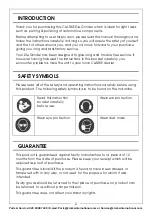
Page 2: ...arefully you encounter problems take the unit to your local CLARKE dealer SAFETY SYMBOLS Please read all of the safety and operating instructions carefully before using this product The following safe...

Page 3: ...tors and a dust mask when using the air tool 4 Do not overreach Keep proper footing and balance at all times 5 Never use oxygen CO2 combustible gases or any type of bottled gas as a source of power fo...

Page 4: ...e tool They add weight and could fail due to vibration 19 Do not force or misuse the tool It will do a better and safer job at the rate for which it was designed 20 Do not remove any labels Damaged la...

Page 5: ...items shown When opening the carton for the first time check against the following list that all the items are present Any damage or deficiency should be reported to your CLARKE dealer immediately NO...

Page 6: ...ulator is used it will keep the tool in good condition but should be regularly checked and topped up with oil SAE 10 oil should be used and the lubricator adjusted to approx 2 drops per minute Use onl...

Page 7: ...he compressor daily and the inlet filter is kept clean If an unusually long air hose is required over 8 metres the line pressure or the hose inside diameter may need to be increased The air hose must...

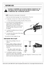
Page 8: ...y 4 Connect a suitable hose to the air inlet as shown 5 Connect the other end of the hose to the compressor Your air tool is now ready for use INSTALLING THE COLLET 1 Select the grinding stone you req...

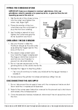
Page 9: ...le locking lever forward while squeezing the trigger against the body of the tool 2 The speed is dependant upon how hard the trigger is depressed The trigger cannot be locked on and has a lock off dev...

Page 10: ...cking mechanism due to lack of lubricant 1 Reduce the force applied to the tool 2 Return to Clarke dealer for repair 3 Drip air tool lubricating oil into air inlet Allow oil to soak moving parts befor...

Page 11: ...ND REPAIR If the tool runs erratically or becomes inefficient although the air supply is in good order it may be necessary to dismantle the air motor and replace any worn or damaged parts Such servici...

Page 12: ...ational reserve the right to change specifications at any time without prior notice Always consult the machine s data plate Model Number CAT146 Tool Dimensions L x W x H 125 x 67 x 45 mm Tool Weight 0...

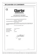
Page 13: ...13 Parts Service 020 8988 7400 E mail Parts clarkeinternational com or Service clarkeinternational com DECLARATION OF CONFORMITY...

Page 14: ...14 Parts Service 020 8988 7400 E mail Parts clarkeinternational com or Service clarkeinternational com PARTS DIAGRAM...

Page 15: ...Pin 21 Pin 4 Lever 22 Rotor 5 Spring 23 Rotor Blade 6 Trigger Pin 24 Cylinder 7 Air Inlet 25 Rotor Collar 8 Soft Grip 26 Front Plate 9 O Ring 27 Pin 10 O Ring 28 Bearing 11 Valve Stem 29 Valve Bushin...

Page 16: ......

Reviews: