background image

Clarke

®


 American Sanders

  B-2    (CE)  Operator's  Manual

                       FORM NO. 70162B - 11 -

Figure 9

Figure 10

Figure 11

MAINTENANCE

Lubrication

The machine is completely lubricated.  The bearings and
gears in the gear unit have enough lubricant for approximately
six months of normal operation.  All other bearings are sealed
and have enough lubricant for the life of the machine.  No
lubricant is needed for the rotating disc guard.

How To Change The Lubricant In The Gearbox

To change the lubricant in the gearbox, follow this procedure:

1. Put the machine upside down on a bench.
2. Align one of the two holes in the rubber pad with one of

the three holes in the rotating disc guard.

3. Align both holes with one of the three screws in the

gear housing cover.  Remove the screw from the gear
housing cover.  See figure 9.

4. Align the holes with each of the other two screws, then

remove screws.

CAUTION

:

Make sure no dust enters the gear
box.  Damage could occur to the gear
box.

5. Remove the cover from the gear housing.
6. Remove the old lubricant from the gearbox.
7. Add ten ounces of Clarke American Sanders lubricant

to the gearbox.

CAUTION

:

To prevent damage to the motor,
do not add more than ten ounces
of lubricant to the gearbox.

8. Using the three screws removed above, install the cover

on the gear housing.

9. Start the machine and let it run for 15 minutes.  A small

amount of excess lubricant should flow out the vent
hole.  If none appears it may be necessary to add
additional lubricant.

10. Wipe off excess lubricant and clear vent hole.

How To Check The Carbon Brushes

Depending on use, a set of brushes can be expected to last
250 hours and should be inspected sometime prior to that
time.

To check the brushes, follow this procedure:

1. Remove the motor cover.  See figure 10.
2. Inspect the carbon brushes.  Replace both brushes if

either brush has worn to 3/8" in length, or is worn to the
wear indicator.  See figure 11.

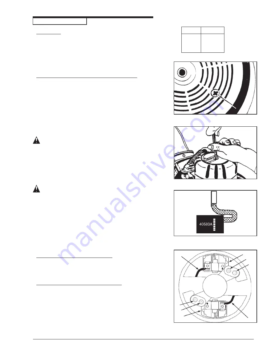
3. To replace the brushes, disconnect the field wire (A)

from the brush holder (B).  Then remove the two screws
and washers (C) securing the holder to the motor
housing.  See figure 12.

Lubricants

Qty

Part No.

1 Qt.

16610A

1 Gal.

16611A

Figure 12

A

A

B

B

C

C

C

C

Summary of Contents for 07097A

Page 1: ...gan 48906 Fax 517 484 9836 Email CustServe Michco com Web site www Michco Com Parts Web site www FloorMachineParts Com Order Parts on Line at www FloorMachineParts Com Directly to Parts Service By Email Shop Michco com By Fax 517 702 2041 By Voice Use numbers above Serving the Cleaning Industry Since 1922 Notice All copyrighted material remains property of original owners all trademarks are proper...

Page 2: ...ou must have training in the operation of this machine before using it If your operator s cannot read English have this manual explained fully before attempting to operate this machine Si Ud o sus operadores no pueden leer el Inglés se hagan explicar este manual completamente antes de tratar el manejo o servicio de esta máquina All directions given in this book are as seen from the operator s posi...

Page 3: ...WARNING TheProductssoldwiththisManualcontainormaycontainchemicalsthatareknowntocertaingovernments suchastheStateof California asidentifiedinitsProposition65RegulatoryWarningLaw tocausecancer birthdefectsorotherreproductiveharm In certainlocations includingtheStateofCalifornia purchasersoftheseProductsthatplacetheminserviceatanemploymentjobsiteora publiclyaccessiblespacearerequiredbyregulationtomak...

Page 4: ...d this manual have it explained fully before they attempt to use this equip ment DANGER Sanding finishing wood floors can create an environment that can be explosive The following safety procedures must be adhered to Cigarette lighters pilot lights and any other source of ignition can create an explosion when active during a sanding session All sources of ignition should be extinguished or removed...

Page 5: ... cord over the sanding equipment Do not use the electrical cord to move the sanding equipment Disconnect the electrical source before servicing this equipment WARNING Injury to the operator or bystander can occur if protective gear is not worn while sanding Always use eye ear and respiratory protection while performing any sanding operation WARNING Bodily injury could occur if power is applied to ...

Page 6: ...tects the rubber pad permitting the edger to work right up to the baseboard or wall Specifications Voltage Frequency 220V 240 50 60Hz Amperage 6 5 Motor 1450W 1 HP Sound Level 91dB A Vibration 5 7 m s2 rms Abrasive Size 178mm x 22 mm Dia 7 x 7 8 Dia Disc Rate High 3200RPM Disc Rate Low 2800RPM Gears Hardened steel alloy pinion anddrivegear Bearings Sealed ball bearings lifetimelubricated DustColle...

Page 7: ...stem beforeoperation Preparing to use the included dust bag To prepare the machine for use with the included dust bag Part No 53544B follow this procedure 1 Install the dust bag by pressing the end onto the exhaust tube until the ring locks into the groove figure 2 This is best done by pressing on the back of the bag opening with the palm of your hand 2 The exhaust tube can be rotated for optimum ...

Page 8: ... With the wrench supplied remove the screw and abrasive retainer Hold pad to prevent it from rotating and turn wrench See figure 3 3 Center abrasive on pad and install the abrasive retainer and screw Tighten screw 4 Return machine to upright position WARNING Serious injury could occur when attempting to replace abrasive while machine is connected to power supply Always disconnectpowerbeforeinstall...

Page 9: ...orward and sideway motions In time you will develop your own technique to optimize coverage and dust control It is advisable to not add effort to the pad as this may lead to nosing or tipping which produces grooves or lines on the floor 6 When replacing abrasive emptying the contents of the dust bag or the sanding operation is completed return the machine to the reclined position and flip the cont...

Page 10: ...loor making admission of a stain difficult If glazing or burning should occur immediately into a finishing cut increase pace If it should occur during a finishing cut the abrasive has dulled and must be replaced 12 grit Forremovinggrossimperfectionsandrestoreevenness 16 grit to old flooring To remove build up of paints and varnishes 20 grit 30 grit For first sanding of new flooring maple oak For r...

Page 11: ...the exhaust pipe to the housing See figure 5 2 Remove the obstruction from the exhaust pipe 3 Install the exhaust pipe How to Adjust the Angle Of The Sandpaper Disc To The Floor The adjustment of the machine is correct when the front part of the sandpaper disc makes contact with the floor To change the adjustment of the machine follow thisprocedure 1 Using the special wrench loosen the lock nut on...

Page 12: ...mthegearhousing 6 Remove the old lubricant from the gearbox 7 Add ten ounces of Clarke American Sanders lubricant to the gearbox CAUTION To prevent damage to the motor do not add more than ten ounces of lubricant to the gearbox 8 Using the three screws removed above install the cover on the gear housing 9 Start the machine and let it run for 15 minutes A small amount of excess lubricant should flo...

Page 13: ...pring and brush holder guide Take care not to damage the spring See figure 13 8 Depress the brush into the guide and connec the shunt wire to the holder 9 Depress the brush and insert the holder into the motorhousing 10 Rotate holder beneath motor housing Relax brush against commutator 11 Align posts on holder with holes in housing 12 Gently pry the holder into the housing 13 Reattach screws and w...

Page 14: ...erican Sanders B 2 CE Operator s Manual FORM NO 70162B 13 B2 B2 B2 B2 B2 7 Spinner 7 Spinner 7 Spinner 7 Spinner 7 Spinner Edger CE Edger CE Edger CE Edger CE Edger CE Section II Parts and Service Manual 70162B ...

Page 15: ...2B Clarke American Sanders B 2 CE Operator s Manual Model B 2 7 Spinner Edger CE Drawing 1 1 2 3 4 3 5 6 8 7 9 10 11 12 13 14 19 15 16 19 17 18 42 38 39 40 41 20 21 22 23 24 25 26 27 28 29 30 31 32 33 34 43 35 36 37 44 ...

Page 16: ...earing 1 Ref Part No Description Qty Ref PartNo Description Qty Model B 2 7 Spinner Edger CE Parts List 1 22 61568A Gear 1 23 67426A Shaft 1 24 915028 Key 1 25 57702A Ring Retaining 1 26 58114A Seal Oil 1 27 902550 Bearing 1 28 34232A Gasket 1 29 12906A Cover Gearcase 1 30 59817A Washer 1 4 Nylon Countersink 3 31 962098 Screw 20 x 3 4 Fit Hd 3 32 15000A Guard Roller 1 33 66917A Retainer 1 34 39707...

Page 17: ... American Sanders B 2 CE Operator s Manual Model B 2 7 Spinner Edger CE Drawing 2 3 4 5 6 2 7 1 8 11 12 56 9 10 13 57 55 54 10 50 51 52 44 53 9 10 42 41 14 49 15 16 47 44 17 34 33 32 23 24 25 31 25 26 27 28 29 30 21 46 45 43 48 ...

Page 18: ...r Housing 1 57 50827A Enclosure 1 30050A Case Carrying 1 56380639 Decal Prop 65 1 56380216 Decal Power Tool Warning 1 Not Shown New or Revised Since Last Update Model B 2 7 Spinner Edger CE Parts List 2 Ref Part No Description Qty Ref PartNo Description Qty 1 39305A Tubing 1 2 962823 Screw 1 4 20 x 1 2 2 3 68705A Wrench Special 1 4 64601A Holder Wrench 2 5 47365A Switch Rocker 1 6 40114A Switch Pu...

Page 19: ... 18 FORM NO 70162B Clarke American Sanders B 2 CE Operator s Manual Model B 2 7 Spinner Edger CE Wiring Diagram 11 99 ...

Page 20: ......

Page 21: ...A Nilfisk Advance Brand 14600 21st Avenue North Plymouth MN 55447 3408 www clarkeus com Phone 800 253 0367 Fax 800 825 2753 2010 Nilfisk Advance Inc ...

Reviews: