background image

[SM-213928-A/2]

35

SPECIFICATION

HOW TO ORDER

8.  PRODUCT SPECIFICATIONS AND HOW TO ORDER 

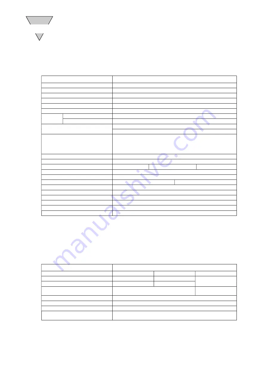
8.1  Product Specifications 

1)  Specifications of the Block Manifold 

Item 

Specifications 

Manifold 

Block manifold (DIN rail mount) 

Applicable solenoid valve 

(N) 4KB2 Series (not including the external pilot series) 

No. of stations 

2 to 25 

Valve type and operation 

Pilot operated soft spool valve 

Working fluid 

Compressed Air 

Piping method(Note1) 

Common air supply (P), common exhaust (R) 

Port size 

Air supply exhaust P

Top (

φ

8, 

φ

10

、φ

12 push-in joint) 

Cylinder port A

Side (

φ

6, 

φ

8, 

φ

10 push-in joint) 

Tube to be used 

Soft nylon (F-15 Series) 

Urethane (U-95 Series), New urethane (UN Series) 

Flow characteristics C(Sonic conduct-

ance)                                            dm

3

/(s

bar)

4KB210,4KB220:2.6 

4KB230:2.4 
4KB240:3.1 
4KB250:2.3 

Ambient temperature 

5 to 50 

Fluid temperature 

5 to 50 

Min. working pressure 

MPa

0.15(2-pos.single)                                       

0.10(2-pos.double) 

0.20(3-pos.) 

Max. working pressure 

MPa

0.70 

Proof pressure 

MPa

1.05 

Response time 

ms

30 or less(2-pos) 

60 or less(3-pos) 

Lubrication 

Not required (Use Grade turbine oil type 1. ISO VG 32 when required)

Protection structure 

Dust-proof 

Vibration resistance

m/s

2

50 or less 

Shock resistance

m/s

2

300 or less 

Atmosphere

No corrosive gas should exist 

Manual operating device 

Non-locking type (Option : locking) 

Above-mentioned response time is the figure on the non-lubricated at 0.5 MPa , 

and depends on the pressure and quality of lubricant. 

Pressure is converted as 1MPa=10.1972kgf/cm

2

10.2kgf/cm

2

In case of use, consult separately of the continuous energizing. 

  Note1

Common pilot exhaust(except pilot exhaust of 3-position) 

2) Electrical Specifications 

Item 

Specifications 

Rated voltage 

V

AC100V (50 / 60Hz) 

AC200V (50 / 60Hz) 

DC24V 

Starting current 

A

0.056 / 0.044 

0.028 / 0.022 

0.075 

Holding current 

A

0.028 / 0.022 

0.014 / 0.011 

Power consumption (with indicator 

light) 

W

1.8 / 1.4 (1.8 / 1.5) 

1.8 (2.0) 

Voltage fluctuation range 

±

10% 

Thermal class 

B(mold coil) 

Temperature rise 

43 

Electric connection 

Grommet with lead wire 

(option : small terminal box, C-connector, D-connector) 

Summary of Contents for MN4KB2 Series

Page 1: ...ANIFOLD MN4KB2 SERIES Please read this instruction manual carefully before using this product particularly the section describing safety Retain this instruction manual with the product for further consultation whenever necessary 2nd Edition ...

Page 2: ...s product is intended for use in general industrial devices and parts Use beyond such conditions is not considered Consult with CKD for details when using the product beyond the unique specification range outdoors or in the following conditions or environments In any case measures for safety shall be provided when the vavle malfunctions Use for special applications requiring safety including nucle...

Page 3: ...eumatic components make sure that system safety such as pop out prevention measures is secured 5 Observe warnings and cautions on the pages below to prevent accidents The safety cautions are ranked as DANGER WARNING and CAUTION in this section When a dangerous situation may occur if handling is mistaken leading to fatal or serious injuries or when there is a high degree of emergency to a warning W...

Page 4: ...ond those stated in the catalogue or specifications Failure resulting from malfunction of the equipment and or machine manufactured by other companies Failure resulting from wrong use of the product Failure resulting from modification or repairing that CKD CORPORATION is not involved in Failure resulting from causes that could not be foreseen by the technology available at the time of delivery Fai...

Page 5: ...lenoid valve system dry Take care to avoid direct contact with dripping water or splashes of cutting oil If the solenoid valve system is wet by a direct contact with water or cutting oil an electrical leak or burnt sole noid coils may result Protect the solenoid valve system by using a cover or by installing it inside a paneled casing If the cylinder rod is splashed with cutting oil the oil may pe...

Page 6: ...king and gaskets may deteriorate sooner than usual if used in an atmosphere with a higher than normal density of ozone for example the atmosphere near a beach or in an area with frequent thunder storms Consult us for the packing and gaskets to be used in an atmosphere with a higher ozone density INSTALLATION Section 4 2 When installing a solenoid valve unit never attempt to hold it in position by ...

Page 7: ...hly pressurized air may disconnect pipes at joints and or cause the tubes to jump around any of which may cause an injury d Do not decrease the inside diameter of the piping from any of the solenoid valve exhaust ports to a diameter less than the exhaust pipe connecting port size Normal operation of the actuator depends on the smoothness of the exhaust flow With a manifold system a restriction to ...

Page 8: ...r the cylinder to be acti vated AIR QUALITY Section 5 3 a Do not supply anything other than compressed air b Supply clean compressed air without any mixture of corrosive gas a Compressed air usually contains a large amount of drain oxidized oil tar foreign matter and rust from the piping Filter out those elements in the supplied air because they may cause a malfunction and de crease service life I...

Page 9: ...rm the ab sence of residual pressure The above is required to ensure safety Regularly perform the daily and periodic inspections to correctly maintain product performance If the product is not correctly maintained product per formance may deteriorate dramatically resulting in a shorter service life fractures of components and mal functions DISASSEMBLING AND REASSEMBLING Section 6 2 Before disassem...

Page 10: ...hod 14 4 3 Piping 15 4 4 Wiring 18 5 OPERATING RECOMMENDATION 5 1 Operation 24 5 2 Manual operating device 26 5 3 Air Quality 27 5 4 Electric Circuits 29 6 MAINTENANCE 6 1 Periodic Inspection 30 6 2 Disassembling and Reassembling 31 7 TROUBLE SHOOTING 34 8 PRODUCT SPECIFICATIONS AND HOW TO ORDER 8 1 Product Specifications 35 8 2 How to Order 36 8 3 Accessory 39 8 4 Consumable parts 43 ...

Page 11: ...nnecting key The key is pushed in after the connection of the blocks in order to secure the connection Mounting screw DIN rail on the manifold DIN rail End block It has a function of common supply exhaust flow plug ging Riping adapter one touch joint Port P is the supply port Port R and PR is the ex haust port Port A and B is the output port Valve block A block of assembled solenoid valve unit and...

Page 12: ...04 9 80665 10 2 1 10 2 1 Note 1Pa 1N m2 1MPa 1N mm2 Pressure Pa kPa MPa bar kgf cm2 atm mmH2O mmHg or Torr 1 1 10 3 1 10 6 1 10 5 1 01972 10 5 9 86923 10 6 1 01972 10 1 7 50062 10 3 1 103 1 1 10 3 1 10 2 1 01972 10 2 9 86923 10 3 1 01972 102 7 50062 1 106 1 103 1 1 10 1 01972 10 9 86923 1 01972 105 7 50062 103 1 105 1 102 1 10 1 1 1 01972 9 86923 10 1 1 01972 104 7 50062 102 9 80665 104 9 80665 10...

Page 13: ...he valves are ready to be con nected to the pipes the entry of foreign matter from the piping ports could cause the solenoid valves to fail or malfunction a Check the model number imprinted on the product to make sure that the product you received is exactly the product you ordered b Check the exterior of the product for any damage c Before using the product read the supplied documentation CAUTION...

Page 14: ...sult Protect the solenoid valve system by using a cover or by installing it inside a paneled casing If the cylinder rod is splashed with cutting oil the oil may penetrate through the cylinder into the secondary side piping of the solenoid valve This must be prevented to avoid malfunctions Consult us for preventive measures c The coils will produce heat Particularly if the solenoid valve system is ...

Page 15: ...a with frequent thunder storms Consult us for the packing and gaskets to be used in an atmosphere with a higher ozone density 4 2 Installation method When installing a solenoid valve unit never attempt to hold it in position by means of the pipes connected to it Mount the solenoid valve by applying the mounting screws and or mounting plate to the solenoid valve 4 2 1 A work space for installation ...

Page 16: ... highly pressurized air may disconnect pipes at joints and or cause the tubes to jump around any of which may cause an injury d Do not decrease the inside diameter of the piping from any of the solenoid valve exhaust ports to a diameter less than the exhaust pipe connecting port size Normal operation of the actuator depends on the smoothness of the exhaust flow With a manifold system a restriction...

Page 17: ... delay hap pens the speed needs to be adjusted between the cylinder and solenoid valve 4 3 4 Pipe connections 1 Tubes to be used For use with solenoid valves with one touch joints select tubes of the type specified by us Soft nylon tubes F 1500 Series Urethane tubes U 9500 Series 2 For installation at a site that has spatters in the air select incombustible tubes or metal pipes 3 For a piping used...

Page 18: ...ubes Neglecting the minimum bending radius may cause disconnection or leaks Tube bore Minimum bending radius mm Nylon Urethane φ4 10 10 φ6 20 20 φ8 30 30 φ10 40 40 6 Cutting a tube To cut a tube use a tube cutter to cut the tube perpendicularly to the length of the tube Inserting an obliquely cut end of a tube may cause air leakage 7 Tube connections Do not bend a tube immediately at where it is c...

Page 19: ...voltage and the current type AC or DC 1 Caution for wiring 1 When using the small terminal box and water proof is required use cab tire cords φ4 to φ6 5 in outer diameter water resistance is improved but not for outdoor use 2 The connector type C C1 C2 C3 D D1 D2 D3 should be used in a place with little dust and not directly exposed to water and oil 3 For the electrical circuit use a switching cir...

Page 20: ...o code B L LS Shape Circuit Name Plug in connector C type with lead wire Plug in connector C type without lead wire Plug in connector C type with lead wire surge suppressor and indicator light Plug in connector C type without leadwire surge suppressor and indicator light Option code C C1 C2 C3 Shape Circuit DC AC AC Lead wire 300mm 11 0 16 Lead wire 300mm 11 0 16 DC Red Black AC Lead wire300mm 20 ...

Page 21: ...essor and indicator light Plug in connector D type without leadwire surge suppressor and indicator light Option code D D1 D2 D3 Shape Circuit Name Surge suppressor attached Option code S Shape DC only grommet lead wire AC DC other than grommet lead wire type Circuit The surge suppressor has polarity Lead wire 300mm 11 0 16 Lead wire 300mm 11 0 16 DC Red Black AC Red Black ...

Page 22: ...ts No 4K9 013 Caulking tool Tyco Electronics Japan 720781 3 Earth terminal Coil Lead wire 0 3 to 0 75mm2 Cabtyre cord JIS C3306VCTF 2 cord Outside diameter φ4 to 6 5 Cap Washer Gasket Pin support Case Selective 4 position in 90 apart available Gasket Screw Slide the gasket and pin support over live terminals and earth terminal Insert caulked terminals to the pin support Tighten the cap after placi...

Page 23: ...stinguish plus or minus Lead wire 0 3 to 0 75mm2 Connect element wire with screw It may be necessary to provide a small standard driver Eliminate connecting surge suppressor together Slide the gasket and terminal block over live terminals and earth terminal Tighten screw after placing case over Gasket Terminal block Case Selective 4 position in 90 apart available Gasket Washer Tightening torque 0 ...

Page 24: ...terminal made by CKD Caulking tool made by CKD Lead wire AWG22 to 25 0 16 to 0 38mm2 Terminal caulking Insert both caulked terminals into the slots farthest apart Insert a socket Insert a gasket and connector Tightening screw Plug in connector D type Insert a socket Gasket Built in Surge suppressor And Indicator light available Coil ass y 180 180 Tightening screw Tightening torque 0 3N m Plug in c...

Page 25: ...Air supply from P to B Exhaust from A to R Air supply from P to A Exhaust from B to R 4KB229 Air supply from P to A Exhaust from B to R 4KB239 Closed P A B R 4KB249 Closed P Exhaust from A B to R 4KB259 Air supply from P to A B Closed R 4KB229 4KB219 4KB239 4KB249 4KB259 R port color White P port color Green A port color Green B port color White ...

Page 26: ...e 2 The adjoining cylinder may pop out by back pressure when driving the sin gle acting cylinder with 3 position A B R parts connected 4KB240 or 3 port valve in the manifold To prevent this use the unit only for the solenoid valve of this circuit or activate another solenoid valve after energizing this solenoid valve 3 Use pipes for the P port matching the port size of the manifold The lack of flo...

Page 27: ...ormally return to OFF position 1 Manual operating device As this is a pilot solenoid valve the spool will not be switched by operating the manual operating device without an air supply to the P port 2 Non lock type manual operating device Push in the manual axis all the way With the 3 position single solenoid the valve is energized while the axis is being pressed and it returns to the origi nal st...

Page 28: ...nction 5 3 1 Lubrication The MN4KB2 Series solenoid valve systems use pre lubricated valves that usually do not require lubrication from the outside If you have to lubricate a valve use Type 1 turbine oil ISO VG32 without additives Excessive lubrication and extremely low pressure may cause a longer re sponse time The response time in the catalogue assumes no lubrication from the outside and the ai...

Page 29: ... oil wear of the sliding components of the pneumatic device may be acceler ated 2 Supply clean compressed air that does not include solid foreign matter 1 Solid foreign matter in the compressed air may cause wear of the sliding components of the pneumatic device or stick to such components and cause hydraulic lock 5 3 5 Cleaning the supplied air Compressed air usually contains a large amount of dr...

Page 30: ...low A current leak larger than the allowable level may cause an erroneous valve operation 1 With a double solenoid type valve system energize the solenoid for at least 0 1 second even for an instantaneous valve operation If the target valve can be affected by a back pressure induced by another solenoid valve it is recommendable to energize the solenoid as long as the cylinder is making an action 2...

Page 31: ...n from the air filters 1 Checking the compressed air supply pressure Is the supply pressure at the specified level Does the pressure gauge indicate the specified pressure when the system is operating 2 Checking the air filters Is the drain normally discharged Is the amount of dirt attached to the bowl and element at a normal level 3 Checking joints in the piping for the leakage of compressed air A...

Page 32: ... solenoid valve system needs to have a knowledge for safely per forming such operation based on the understanding about the mechanisms and operating principles of solenoid valves 6 2 1 Solenoid valve mounting and detaching Solenoid valve setting 1 Fit the valve block with the gasket 2 Mount the solenoid valve on the valve block and fasten it with the two screws at 0 5N m WARNING Valve unit mountig...

Page 33: ...d block mounting 1 First confirm that the fixing screws are loose Push the block from above and get the movable claw hooked onto the rail 2 Lift the block to see the claw is firmly in place 3 Tighten the two screws at the torque of 0 9 N m after all the other blocks are set 3 End block detaching 1 Turn the screws six to seven times to loosen them and pull out the connecting key 2 Slide the end blo...

Page 34: ...then push the moveble claw from above 2 Slie them until there is no space between the blocks and push in the connecting key 5 Air supply exhaust block valve block detaching 1 Remove the end block 2 Pull out the connecting key 3 Slide the blocks 4mm or more from each other lift the side with the movable claw to remove the block ...

Page 35: ...Install pipe joints to A and B ports with diame ter equal to or smaller than that of to P port joint Valve is frozen Add remedies of avoiding freezing Heating system or dehumidifying system etc Delayed return of a plunger Excessive oil existence of far Check the quality of the lubricant Turbine oil type1 ISO VG 32 or equivalent Rectify the quantity of lubricant drip Install a tar removing filter C...

Page 36: ...re MPa 0 70 Proof pressure MPa 1 05 Response time ms 30 or less 2 pos 60 or less 3 pos Lubrication Not required Use Grade turbine oil type 1 ISO VG 32 when required Protection structure Dust proof Vibration resistance m s2 50 or less Shock resistance m s2 300 or less Atmosphere No corrosive gas should exist Manual operating device Non locking type Option locking Above mentioned response time is th...

Page 37: ...x with indicator light No option 25 25 stations LS Small terminal box with surge suppressor and indica tor light No option C Plug in connector C type 300mm C00 500mm C01 1000mm g Voltage C02 2000mm Code Description C03 3000mm AC100V AC100V 50 60Hz Standard C1 No option AC200V AC200V 50 60Hz C2 Plug in connector C type with surge suppressor and indica tor light 300mm DC24V DC24V C20 500mm AC24V AC2...

Page 38: ...s by model after the ordinary model description Also state after the model description the marking see the table of necessary functions and position numbers starting with 1 on the left side until the specified number of stations in the manner as shown below Code Function 1 2 position single S1 S1 2 pos single operator 2 2 position single S1 S2 2 pos double operator 3 2 position single S1 S3 3 pos ...

Page 39: ...n connector C type with surge suppressor and indi cator light 300mm DC24V DC24V C20 500mm AC24V AC24V 50 60Hz Option C21 1000mm AC110V AC110V 50 60Hz C22 2000mm AC115V AC115V 50 60Hz C23 3000mm AC120V AC120V 50 60Hz C3 No option AC220V AC220V 50 60Hz D Plug in connector D type 300mm DC12V DC12V D00 500mm D01 1000mm D02 2000mm D03 3000mm D1 No option D2 Plug in connector D type with surge suppresso...

Page 40: ...ription N4KB2 NE1 Left side end block Model no Description N4KB2 NE2 Right side end block 2 Air supply exhaust block NQ Model no P port R port N4KB2 2NQSH12 φ12 φ12 N4KB2 2NQSH10 φ10 φ10 N4KB2 2NQSH8 φ8 φ8 Model no P port R port N4KB2 2NQUH12 φ12 φ12 N4KB2 2NQUH10 φ10 φ10 N4KB2 2NQUH8 φ8 φ8 ...

Page 41: ...ort N4KB2 2NPSH12 φ12 N4KB2 2NPSH10 φ10 N4KB2 2NPSH8 φ8 Model no P port N4KB2 2NPUH12 φ12 N4KB2 2NPUH10 φ10 N4KB2 2NPUH8 φ8 4 Exhaust block NR Model no P port N4KB2 2NRSH12 φ12 N4KB2 2NRSH10 φ10 N4KB2 2NRSH8 φ8 Model no P port N4KB2 2NRUH12 φ12 N4KB2 2NRUH10 φ10 N4KB2 2NRUH8 φ8 ...

Page 42: ... no A B port N4KB2 2NS2SH10 φ10 N4KB2 2NS2SH8 φ8 N4KB2 2NS2SH6 φ6 NS is provided according to a Solenoid position When changing solenoid position NS should be changed 6 Partition block NC Model no Description N4KB2 NC1 All port closed Model no Description N4KB2 2NC2 Exhaust port closed PR R P PR Solenoid valve A port B port PR R P PR Solenoid valve A port B port PR R P PR PR R P PR ...

Page 43: ... no L BAA500 500 BAA1000 1000 Silencer Model no D L B A SLW H8 φ8 42 23 20 16 SLW H10 φ10 53 31 5 27 20 SLW H12 φ12 66 43 37 25 Blank plug Model no D L d GWP6 B φ6 29 11 5 8 GWP8 B φ8 33 14 10 GWP10 B φ10 40 18 5 12 GWP12 B φ12 43 20 14 B L φ D φ A φ d L φ D 12 5 Pitch 8 L 7 5 5 5 25 35 ...

Page 44: ... 4KB210 4K9 150 4KB210 4K9 153 4KB220 4K9 126 4KB220 4KB230 4K9 127 4KB230 4K9 154 4KB240 4K9 128 4KB240 4KB250 4K9 129 4KB250 3 Coil assembly Function Model example All model common 4K1L COIL 4 Gasket kit Function Model example MN4KB21 MN4KB210 GASKET KIT S MN4KB22 MN4KB210 GASKET KIT D MN4KB23 MN4KB24 MN4KB25 Voltage Electrical connection option ...

Reviews: