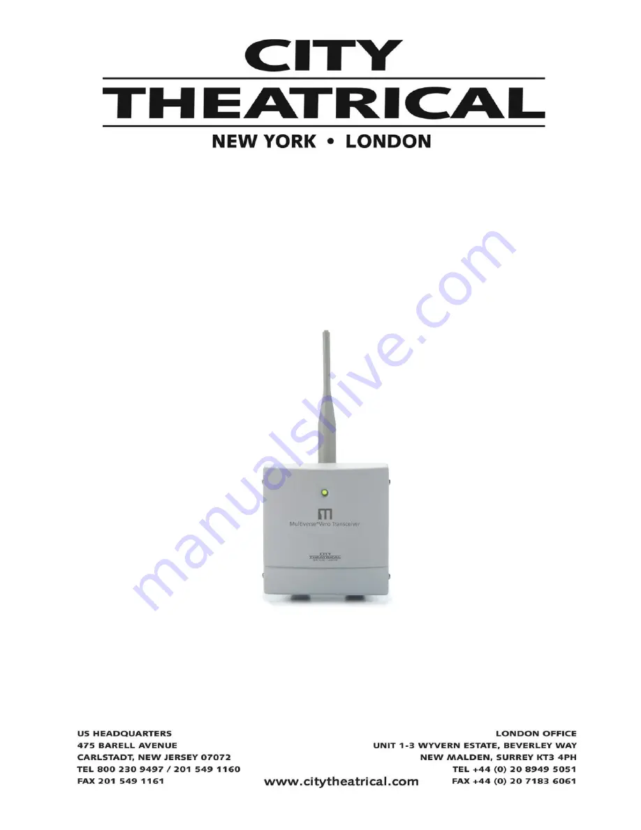
background image


Multiverse

®

 Vero Transceiver                             

900MHz/2.4GHz 

P/N 7400-5902 

User’s Manual 

Rev 1.0 


© 2021 City Theatrical, Inc. 


Multiverse Transmitters are covered by U.S. Patents #7,432,803 B2,  #10,129,964 B1, 

and other patents pending.  


This product is licensed for use in North America only. 


Made in USA 

Summary of Contents for 7400-5902

Page 1: ... 4GHz P N 7400 5902 User s Manual Rev 1 0 2021 City Theatrical Inc Multiverse Transmitters are covered by U S Patents 7 432 803 B2 10 129 964 B1 and other patents pending This product is licensed for use in North America only Made in USA ...

Page 2: ...2 Updating Firmware 12 What s Included 12 Specifications 13 Troubleshooting 14 List of Tables Table 1 Selecting Your Multiverse SHoW ID 10 Table 2 SHoW IDs and SHoW Keys 12 Table 3 Included Item Descriptions and Part Numbers 13 Table 4 Physical Characteristics 14 Table 5 Troubleshooting Guide 15 Table 6 Legacy SHoW IDs Guide 15 List of Figures Figure 1 Surface Mounting Diagram 6 Figure 2 Face Pane...

Page 3: ...xempts de licence L exploitation est autorisée aux deux conditions suivantes 1 l appareil ne doit pas produire de brouillage et 2 l utilisateur de l appareil doit accepter tout brouillage radioélectrique subi même si le brouillage est susceptible d en compromettre le fonctionnement Safety Notices Please read this entire manual before using your new equipment Please keep the manual in a safe place ...

Page 4: ...ergy mRDM Multiverse is able to broadcast RDM information without disrupting the DMX broadcast This feature is not available even in wired RDM systems SHoW Key Security SHoW Key is an optional three digit code that can be added to the Multiverse SHoW ID that will prevent any other system set on the same SHoW ID from interfering with your system Forward Error Correction Allows the Receiver to detec...

Page 5: ...splay timeout and brightness level A bracket for surface mounting or mounting from a pipe Installation Install the Multiverse Vero Transceiver in a suitable location following the instructions below For best results the antennas in your system must be within sight of each other Warning To avoid electric shock do not energize any circuits before all internal and external electrical and mechanical c...

Page 6: ...ton Head Security Screw in the hole on the left side of the Bracket assembly Figure 1 Surface Mounting Diagram Mounting Orientation The 7400 5902 Multiverse Vero Transceiver must be mounted exclusively in an upright mounting position with the cable entries on the bottom and antenna connector on the top as shown in the drawing above Pipe Mounting The Multiverse Vero Transceiver can also be mounted ...

Page 7: ...nd install the retaining Screw Cable or Conduit Entry The unit enclosure is provided with NPT entry holes fitted with liquid tight cable grips for use with outdoor use cables by installer for power and DMX connection The recommended torque for these cable grips is as follows Locking Nut 40 45 inch pounds Sealing Nut 50 55 inch pounds If outdoor use conduit is used instead it is recommended that th...

Page 8: ...nstalling the Cover The Multiverse Vero Transceiver has a two part cover with the outer plastic cover connected to the inner metal cover with a hinge Install the metal inner cover using the eight provided 6 32 x 375 SS Truss Head Machine Screws Hand install these screws until the screw threads are fully engaged with the mating PEM Nut then tighten to 4 inch pounds The outer cover is then closed an...

Page 9: ... a number called the SHoW ID See the SHoW ID chart on page 10 for a full explanation Using A Spectrum Analyzer To Choose A SHoW ID It is a good practice to utilize a device such as City Theatrical s PN5988 RadioScan Spectrum Analyzer to analyze the spectrum in the area of the broadcast RadioScan is a 900MHz and 2 4GHz spectrum analyzer utilizing a hardware dongle and accompanying software that ena...

Page 10: ...1 1500 Outdoor 300 Indoor 2 2 1500 Outdoor 300 Indoor 3 5 1000 Outdoor 100 Indoor Specifies which sections of the wireless band the frequency hopping utilizes 0 Use full range of 900MHz or 2 4GHz band 1 Use only low band channels 2 Use only mid band channels available for Data Rate 1 only 3 Use only high band channels 4 Use only extreme high band to avoid WiFi 2 4GHz only 5 Adaptive hopping Avoids...

Page 11: ...one bar is marginal Restore Factory Defaults Factory defaults can be restored by holding the Menu and Enter buttons while on the main screen Screen will flicker to signal when default process is complete Default settings are listed below Menu Screen Pressing the Menu button takes you to the Menu screen The Menu Screen displays different information depending on whether Mode is selected as Receiver...

Page 12: ...he last button press The timeout can be set to Off backlight will never timeout or any interval from 10 seconds to 59 minutes 59 seconds Default is 59 minutes 59 seconds After a screen timeout pushing any button will wake up the screen without changing the screen selection Backlight Level Controls Backlight brightness Range is 1 100 Default is 100 Information The Information screen shows the RDM U...

Page 13: ...nufacturer Firmware Versions RDM UID RF Signal Quality and quantity of active Tx slots You can also give each device a unique RDM Device Label to help with identification for configuration and troubleshooting Updating Firmware Firmware updates and instructions for performing them are available on the product pages of the City Theatrical website What s Included Figure 3 What s Included Table 3 Incl...

Page 14: ...terface Internal Backlit four button LCD display Construction NEMA 4 IP66 Aluminum enclosure Electrical Power 90 277VAC input 1A max on 3 pin screw terminals DMX Terminals DMX In and Out via 3 pin screw termnals Operating Temperature 25ºC 60ºC Radio Technology Latency 4 ms average RF Sensitivity 95dBm Loss of Data Behavior Output stops Broadcast Power 3 2mW 10mW 32mW 100mW EIRP Broadcast Modes Ada...

Page 15: ...s connected to the receiver are not responding Check that the Tx and Rx symbols on transmitters and receivers are solid Check that SHoW ID and SHoW Key and optional SHoW Key match on transmitters and receivers Check that universe setting matches on Tx and Rx SHoW DMX Neo SHoW ID Broadcast Location 201 Adaptive hopping 102 Full bandwidth hopping 117 Low band hopping 133 Mid band hopping 149 High ba...

Reviews: