background image

CBM-202PC-04 User’s Manual

31

CITIZEN

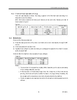
2) Bus Timing

VCC=5.0V±10%, AVCC=5.0V±10%, VREF=4.5V~AVCC, VSS=AVSS=0V, Ø=2~16MHz,
TA=-20~+75ºC

Item

Symbol

MIN

MAX

Clock cycle time

t cyc

62.5

500

Clock pulse width "LOW" level time

CL

20

-

Clock pulse width "HIGH" level time

CH

20

-

Clock rise time

CR

-

10

Clock fall time

CF

-

10

Address delay time

AD

-

30

Address hold time

AH

10

-

Address strobe delay time

ASD

-

30

Write strobe delay time

WSD

-

30

Strobe delay time

SD

-

30

Write data strobe pulse width 1

WSW1

35

-

Write data strobe pulse width 2

WSW2

65

-

Address setup time 1

AS1

10

-

Address setup time 2

AS2

40

-

Read data setup time

RDS

20

-

Read data hold time

RDH

0

-

Write data delay time

WDD

-

60

Write data setup time 1

WDS1

35

-

Write data setup time 2

WDS2

5

-

Write data hold time

WDH

20

-

Read data access time 1

ACC1

-

55

Read data access time 2

ACC2

-

115

  Unit : ns

Summary of Contents for CBM-202PC-04

Page 1: ...CITIZEN User s Manual CBM 202PC 04 Thermal Printer Mechanical Control LSI Rev 1 00 Newly Issued on 13 July 1998 Japan CBM Corporation Information Systems Div...

Page 2: ...up to date specifications 3 It is strictly prohibited to copy part or all of the information contained in this manual without our prior permission 4 If you have any question about the information here...

Page 3: ...1 Absolute Maximum Ratings 8 4 2 Electrical Characteristics 8 4 3 Pin Layout and Functions 9 4 4 Gate Array Pin Layout and Functions 13 4 5 Reset Circuit 14 4 6 Oscillation Circuit 15 4 7 Head up Det...

Page 4: ...36 7 OPERATION TIMING 37 8 SPECIFICATIONS OF PACKAGE 38 9 PRECAUTIONS FOR MOUNTING 39 9 1 Precautions 39 9 2 Reflow Mounting 39 9 3 Recommended Conditions for Different Mounting Methods 39 9 4 Clearin...

Page 5: ...ng printing density 2 Capable of providing high quality printing by detecting a voltage and automatically correcting printing density 3 Capable of selecting the parallel or serial interface 4 Capable...

Page 6: ...t our dealer or at the following address Northern America Other Areas CBM America Corporation Japan CBM Corporation Service Center Information Systems Division 365 Van Ness Way 1 1 7 Okubo Shinjuku ku...

Page 7: ...00 bps Parity Odd Even or None parity 8 bits 3 4 Printing Function 1 Printing columns and printing speed Model Digits Total Dots Character Size mm Printing Speed m s 32 1 25 x3 00 Font A LT 286 42 384...

Page 8: ...AVcc 0 3V Operating temperature Topr 20 75 C Storage temperature Tstg 55 125 C 4 2 Electrical Characteristics Item Symbol MIN MAX Unit Condition RES STBY NM1 MD0 MD1 MD2 Vcc 0 7 Vcc 0 3 V EXTAL Vcc X...

Page 9: ...10 RES0 Output Watchdog output LOW 11 VSS GND 12 DTR Output Serial DTR RS 232C HIGH 13 TXD Output Serial TXD RS 232C HIGH 14 DI Input Print head output data HIGH 15 RXD Input Serial RXD RS 232C HIGH...

Page 10: ...IGH 32 D5 I O D5 HIGH 33 D6 I O D6 HIGH 34 D7 I O D7 HIGH 35 VCC VCC 36 A0 Output A0 HIGH 37 A1 Output A1 HIGH 38 A2 Output A2 HIGH 39 A3 Output A3 HIGH 40 A4 Output A4 HIGH 41 A5 Output A5 HIGH 42 A6...

Page 11: ...ut NC 60 P62 Output NC 61 Output Clock output HIGH 62 STBY Input Pull up to VCC at 10k LOW 63 RES Input Reset input LOW 64 NMI Input Pull up to VCC at 10k LOW 65 VSS GND 66 EXTAL EXTAL 16MHz 67 XTAL X...

Page 12: ...ll down to GND at 10k 85 NC Input Pull down to GND at 10k 86 AVSS GND 87 STB Input Parallel data interrupt LOW 88 HEADUP Input Head up detection terminal LOW 89 CS2 Output Gate Array chip select LOW 9...

Page 13: ...t data D4 HIGH 48 D3 Input Parallel input data D3 HIGH 49 D2 Input Parallel input data D2 HIGH 50 D1 Input Parallel input data D1 HIGH 51 D0 Input Parallel input data D0 HIGH 52 STROBE Input Parallel...

Page 14: ...e reset state is effectuated by setting the RES terminal to Low To surely reset it is necessary to set it to Low at least for 20ms at power on and for 625ns while operating If an external reset is not...

Page 15: ...internal clock There are two methods to supply a clock one is to connect a ceramic oscillator and the other is to input an external clock When using the ceramic oscillator we recommend the CSTCS16 00M...

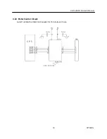
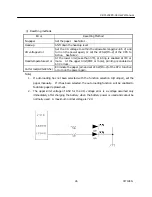
Page 16: ...ter so that the printer will not be energized on with the head up The circuit is opened when the print head is up and closed when down When the print head is up HEADUP Pin 88 of the CPU is turned to H...

Page 17: ...tects a temperature by means of a thermistor included in the printer and determines according to that temperature how much energy should be applied to the printing head If a temperature of the printin...

Page 18: ...ts whether there is the printing paper so that the printer will not be turned on when it has no paper When the printer has no paper PAPER Pin 7 of the CPU is turned to HIGH If printing is under way it...

Page 19: ...CBM 202PC 04 User s Manual 19 CITIZEN 4 10 Motor Control Circuit Avoid running the motor continuously for 15 minutes or more...

Page 20: ...r Control Circuit This CPU has a function to control the auto cutter using the Pin 33 of the Gate Array When the auto cutter is not used set the Pin 33 of the Gate Array to HIGH If set to LOW the prin...

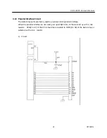
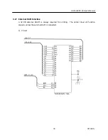
Page 21: ...rray ports are mainly used to provide an 8 bit parallel interface When the parallel interface is not used pull up STB Pin 52 of the Gate Array with a 10k resistor STB Pin 87 of the CPU should be conne...

Page 22: ...ata Positive logic ACK 59 Output A signal to indicate that the data has been read Negative logic BUSY 55 Output A signal to indicate that the data cannot be received Positive logic Send the data when...

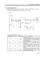
Page 23: ...a reception is disabled when XON XOFF is selected XOFF 13H will be transmitted and if data reception is enabled XON 11H will be transmitted RXD 15 Input Received data signal If a framing error or pari...

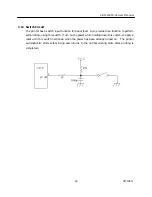
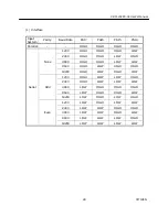
Page 24: ...provided is a function to perform self printing using this switch Turn on the power while holding down this switch or apply a reset with this switch held down when the power has been already turned o...

Page 25: ...Blinks at intervals of 150 ms 6 times and 500 ms 1 time as one cycle Head up Illuminated until the error is reset VH voltage error Illuminated until the error is reset Head temperature error Blinks a...

Page 26: ...At the upper limit 65 C or more printing is enabled at 60 C or less Cutter lock ACS 220 5v Eliminate the paper jam and set LFSW Pin 2 of the CPU to Active or turn on the power again Note 1 If auto loa...

Page 27: ...tter Enabled Disabled 32 PAI1 CR change LF operation Ignored 31 PAI2 Printing density See Table 3 30 PAI3 DTR XON XOFF XON XOFF DTR DSR 29 PAI4 28 PAI5 27 PAI6 26 PAI7 Interface See Table 1 PAI3 is va...

Page 28: ...LOW 2400 HIGH HIGH LOW HIGH 4800 HIGH HIGH LOW LOW 9600 HIGH LOW HIGH HIGH None 19200 HIGH LOW HIGH LOW 1200 HIGH LOW LOW HIGH 2400 HIGH LOW LOW LOW 4800 LOW HIGH HIGH HIGH 9600 LOW HIGH HIGH LOW Odd...

Page 29: ...1 PBI0 Japan JIS HIGH HIGH HIGH Japan Shift JIS HIGH HIGH LOW Sweden HIGH LOW HIGH Denmark I HIGH LOW LOW U K LOW HIGH HIGH Germany LOW HIGH LOW France LOW LOW HIGH U S A LOW LOW LOW 3 Printing densit...

Page 30: ...202PC 04 User s Manual 30 CITIZEN 4 17 External RAM Interface A 32 KB external SRAM is always required for printing The printer does not function properly unless the external RAM is connected 1 Circu...

Page 31: ...30 Address hold time t AH 10 Address strobe delay time t ASD 30 Write strobe delay time t WSD 30 Strobe delay time t SD 30 Write data strobe pulse width 1 t WSW1 35 Write data strobe pulse width 2 t W...

Page 32: ...CBM 202PC 04 User s Manual 32 CITIZEN...

Page 33: ...the printing surface of the printing paper Since the printing head is always driven in the same order this method can assure high quality printing In the Fixed Division Number System the blocks of th...

Page 34: ...nsumption through PWM control 2 Controls acceleration at start time 3 Capable of providing fine control according to a voltage VH applied to the motor to realize optimum paper feed Table 5 1 lists the...

Page 35: ...PE once 2 Insert the printing paper into the printing paper insertion slot until the PE sensor detects the paper again When this is done the paper should be inserted at a right angle to the insertion...

Page 36: ...int Kanji when printing the half size characters or using the specified Kanji ROM CBM 202KG 01 The procedure is as follows 1 Turn on the power setting LFSW Pin 2 of the CPU to LOW Turn on both Vcc and...

Page 37: ...CBM 202PC 04 User s Manual 37 CITIZEN 7 OPERATION TIMINGS The following shows operation timings after resetting this CPU...

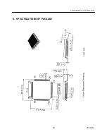
Page 38: ...CBM 202PC 04 User s Manual 38 CITIZEN 8 SPECIFICATIONS OF PACKAGE...

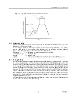
Page 39: ...elted reflow again the leads of the package and the pattern of the PCB will be matched by a self alignment effect through the surface tension of the molten solder Although the lead joint pattern desig...

Page 40: ...e same as in 1 The lower limit is determined by necessity to contain the peak temperature and time mentioned in 4 within the specified ranges 4 Peak temperature and time In order to minimize damages o...

Page 41: ...ng moisture when it is stored in a high humidity place If more moisture is absorbed it will be abruptly vaporized at the time of soldering and cause exfoliation of the resin lead frame interface resul...

Page 42: ...aracter set 1BH 52H n 61 19 ESC V Specifying Canceling 90 right turned Characters 1BH 56H n 62 20 ESC a Aligning the characters 1BH 61H n 63 21 ESC c3 NOP 22 ESC c4 NOP 23 ESC c5 Enabling disabling th...

Page 43: ...EN 43 DC2 A Selecting the Print drive system 12H 41H n 85 Notes 1 In the table n n1 n2 n3 m a s p and d denote the parameters for each command 2 In the table k denotes a repeat count of k times 3 In t...

Page 44: ...times Range Describes an argument value Setting range for the command Outline Describes a command outline Caution Describes a caution as required Default Describes an initial value for the command whe...

Page 45: ...See Also ESC D Sample Program LPRINT 0123456789012345678901 LPRINT CHR HA LPRINT CHR H9 AAA LPRINT CHR H9 BBB LPRINT CHR HA LPRINT CHR H1B D LPRINT CHR 3 CHR 7 CHR 14 CHR 0 LPRINT CHR H9 AAA LPRINT CH...

Page 46: ...rmed See Also LF Sample Program Print Results LPRINT AAA CHR HD LPRINT BBB CHR HD LPRINT CHR HD LPRINT CCC CHR HD ESC SP n Function Setting the right space amount of the character Code 1B H 20 H n Ran...

Page 47: ...double height and double width being specified simultaneously double wide and double high characters are consisted An underline is attached to the full character width which however is not attached t...

Page 48: ...8 CITIZEN Sample Program LPRINT CHR H1B CHR H00 H LPRINT CHR H1B CHR H01 H LPRINT CHR H1B CHR H08 H LPRINT CHR H1B CHR H10 H LPRINT CHR H1B CHR H20 H LPRINT CHR H1B CHR H80 H LPRINT CHR H1B CHR HB9 H...

Page 49: ...an not be defined simultaneously Default n 0 See Also ESC Sample Program GOSUB SETCHR DATA 6 LPRINT CHR H1B CHR 0 DATA HFF H80 H00 LPRINT A CHR HA DATA H80 H80 H00 LPRINT CHR H1B CHR 1 DATA H80 H80 H0...

Page 50: ...inable includes 95 ASCII codes in total between 20 H 7E H a indicates the number of dots in horizontal direction for definition p is the data to be defined which indicate a pattern equal to a dot in h...

Page 51: ...02PC 04 User s Manual 51 CITIZEN Example Create each data bit by setting 1 for a printed dot and 0 for an unprinted dot Sample Program Print Results See Sample Program and Print Results for ESC on Pag...

Page 52: ...een input in excess of dot position of one line 448 dots the excess data are discarded d is bit image data the bits subject to printing are taken as 1 and those not as 0 The bit image modes specified...

Page 53: ...INT CHR 1 CHR 20 CHR 0 NEXT I GOSUB IMG1 LPRINT CHR HFF LPRINT CHR HA RETURN LPRINT CHR H1B IMG2 LPRINT CHR 32 CHR 20 CHR 0 LPRINT CHR HFF GOSUB IMG2 LPRINT CHR HFF LPRINT CHR HA LPRINT CHR HFF LPRINT...

Page 54: ...skipped by horizontal tab command An underline is not attached to a 90 right turned characters Specification cancellation with this command is invalid to Kanji See Also ESC FS Sample Program LPRINT C...

Page 55: ...line The line feed rate per line is specified by n 360 inch Since an actual mechanical pitch is 1 203 inch it is internally converted approximate to the value specified with this command Default The i...

Page 56: ...defined 5 Not defined 6 Not defined 7 Not defined When the printer has not been selected this printer abandons all the received data until it is selected by this command Caution Even when the printer...

Page 57: ...ed in the print buffer and brings various settings to the initial state Default state Caution Data inside the internal input buffer are not cleared Dip switches setting are red once again Sample Progr...

Page 58: ...nary case Tab positions can be specified are maximum 32 Specifying exceeding this is ignored n k which denotes a setting position is input in the increasing order and ends at 00 H ESC D NUL clears all...

Page 59: ...the lowest bit n0 is shown as follows n0 Type 0 Canceling highlighting 1 Specifying highlighting This is effective to all characters Dot configuration of a highlighted character includes one extra do...

Page 60: ...lso ESC E Sample Program LPRINT CHR H1B G CHR 0 LPRINT AAABBB CHR HA LPRINT CHR H1B G CHR 1 LPRINT AAABBB CHR HA Print Results ESC J n Function Printing and feeding paper n 203 inch Code 1B H 4A H n R...

Page 61: ...n Hex Character Set 0 U S A 1 France 2 Germany 3 U K 4 Denmark I 5 Sweden 6 Italy 7 Spain 8 Japan 9 Norway A Denmark II Default The initial value of n indicates the character set specified by the fun...

Page 62: ...ing canceling characters 90 right turned character n means the followings n Hex Condition 0 Canceling 90 right turned Characters 1 Specifying 90 right turned Characters Caution No underlines are attac...

Page 63: ...osition Depending on n value positional alignment is carried out as in the table below n Hex Position 0 Left end alignment 1 Centering 2 Right end alignment Caution This is valid only when n is inputt...

Page 64: ...paper cannot be fed by operating the LF switch Default The initial value of n is 0 Sample Program LPRINT CHR H1B c5 CHR 0 When enabling the LF switch LPRINT CHR H1B c5 CHR 1 When disabling the LF swit...

Page 65: ...inputted at the beginning of line Prior to cutting the paper feed the paper from the printing position to beyond the paper cutting position of the cutter Otherwise the character just after print will...

Page 66: ...is inputted at the beginning of line Prior to cutting the paper feed the paper from the printing position to beyond the paper cutting position of the cutter Otherwise the character just after print w...

Page 67: ...e 0 IBM Character 2 1 Page 1 Domestic Character Default The initial value of n is subject to the character set for the country specified by the function selecting terminal Gate Array Pin 39 42 43 When...

Page 68: ...control DSR signal state not being confirmed only 1 byte is transmitted In DTR DSR control when the host is in unreceptible state DSR signal being in MARK state it waits until receptible state is cre...

Page 69: ...t bit n0 Bit n n0 means the followings n0 Condition 0 Canceling inverted characters 1 Specifying inverted characters Caution Inverted printing means printing the line at 180 turned This is valid only...

Page 70: ...ed by 256 whose quotient is taken as n2 and the residual as n1 Therefore the printing start position is equal to n1 n2 x 256 from the beginning of line Caution Specifying beyond the end of line is ign...

Page 71: ...tion Rightward direction is taken as plus and leftward direction as minus To specify N dot in minus left direction use a complement of N for assignment N dots 65536 N The number of dots is divided by...

Page 72: ...to be required to print a bar code If the character code d cannot be printed in the respective bar code system the bar code so far will be printed processing the subsequent data as normal data When a...

Page 73: ...it is CODE39 This bar code consisting of uppercase alphabets and numerals has a variable length of column A start stop code is automatically added by the printer Available characters include a space a...

Page 74: ...2 N A 98 82h SHIFT SHIFT N A 99 83h CODE C CODE C N A 100 84h CODE B FNC 4 CODE B 101 85h FNC 4 CODE A CODE A 102 86h FNC 1 FNC 1 FNC 1 The following exemplifies a selection of the code subset as a m...

Page 75: ...fixed length bar code consisting of numerals only CODE39 Variable length bar code consisting of alphabets and numerals The start stop code is automatically added 13 ITF Even column variable length ba...

Page 76: ...bar code width n denotes the number of dots in fine element width Default The initial value of this width is 3 Sample Program LPRINT CHR H1D h CHR 30 LPRINT CHR H1D w CHR 2 GOSUB BC LPRINT CHR H1D h C...

Page 77: ...Bar Code Code 1D H 68 H n Range 1 n FF Data is described in Hex code Outline Selecting bar code height n denotes the number of dots in the vertical direction Default The initial value of n is 162 Samp...

Page 78: ...th above and below the bar code The HRI code refers to the bar code turned characters so that you can read them Caution The HRI code is printed in the font selected with GS f Specify before the GS k c...

Page 79: ...Font 0 Font A 1 Font B The HRI code refers to the bar code turned characters so that you can read them Caution The HRI code is printed at the position specified with GS h Default The initial value of...

Page 80: ...dots are n1 x 8 in horizontal direction and n2 x 8 in vertical direction d indicates bit image data The download bit image thus defined remains effective until redefinition ESC execution ESC or power...

Page 81: ...CITIZEN GOSUB IMG LPRINT CHR H1D CHR 0 LPRINT CHR H1D CHR 1 LPRINT CHR H1D CHR 2 LPRINT CHR H1D CHR 3 END IMG n 1 10 n 2 5 LPRINT CHR H1D LPRINT CHR n1 CHR n2 FOR J 1 TO n1 8 FOR I 1 TO n2 LPRINT CHR...

Page 82: ...Double wide mode 203 DPI 101 DPI 2 Double height mode 101 DPI 203 DPI 3 Double wide double height mode 101 DPI 101 DPI Caution When data exist inside the print buffer this command is ignored When a do...

Page 83: ...exceeding 2048 bytes is not defined Even with ESC Initialization of the printer having been executed defined content is not cleared Therefore it is possible to include ESC into the content of macro d...

Page 84: ...ntinuously at the time intervals specified by n2 Execution by LFSW After waiting for lapse of time specified by n2 the Alarm LED flickers and the LF switch is waited to be pressed When it is pressed t...

Page 85: ...nge 0 n FF Outline Selecting the Fixed division system or the Variable division system n is valid only for the lowest bit n0 n0 Print Drive System 0 Fixed Division Number System 1 Variable Division Nu...

Page 86: ...CBM 202PC 04 User s Manual 86 CITIZEN 11 CHARACTER CODE TABLE 11 1 International...

Page 87: ...CBM 202PC 04 User s Manual 87 CITIZEN 11 2 Domestic...

Page 88: ...CBM 202PC 04 User s Manual 88 CITIZEN 11 3 International Character Set...

Reviews: