32 Router Card (WS-X3011) Configuration Note
Reading the LEDs
Verifying Network Connectivity
After you have installed and configured the router, you can use the following commands in user
EXEC mode to verify network connectivity:
•
telnet—Logs in to a remote node
•
ping—Sends a special datagram to the destination device, then waits for a reply datagram from
that device
•
trace—Discovers the routes that packets take when traveling from one router to another
If there is a problem with network connectivity, refer to the section “Reading the LEDs” later in this
document. If there is still a problem, check the switch configuration. Refer to the Catalyst 3X00
Installation and Configuration Guide.
Getting More Information
For more information about router software configuration, refer to the Cisco IOS configuration
guide and command reference publications. These publications are available in the CD ROM that
accompanied your switch, or you can order printed copies. Refer to the section “Ordering
Documentation” at the end of this document.
Reading the LEDs
The LEDs indicate the current operating condition of the router card. You can observe the LEDs,
note any fault condition that the router card is encountering, and then contact your system
administrator or customer service, if necessary. For information about how to contact customer
service, refer to the section “Obtaining Service and Support.”
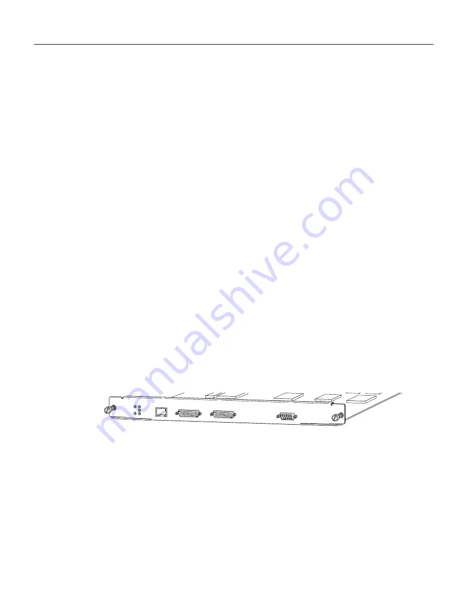
Figure 12 shows the location of the LEDs on the router card. The LEDs are labeled and indicate
activity on a port by flickering. When there is heavy activity on a port, the LED might be ON
constantly. If an LED is not ON when the port is active and the cable is connected correctly, there
might be a problem with the port.
Figure 12
Router Card (WS-X3011) LEDs
Cable, Pinout, and Port Specifications
This section contains the following information:
•
Synchronous Serial Cable Assemblies and Pinouts
•
ISDN BRI Port and Cable Pinouts
H
8506
SERIAL 1
AUX
SERIAL 0
BRI 0
ETH 0
SERIAL 0
SERIAL 1
BRI 0
DIAG
FLEX SLOT
WS-X3011


