background image

S e n d   d o c u m e n t   c o m m e n t s   t o   u c s - d o c f e e d b a c k @ c i s c o . c o m

30

Cisco UCS B440 High Performance Blade Server Installation and Service Note

OL-22475-01

  Memory and Performance

Step 1

Using UCS Manager, perform a graceful shutdown of the server. Without a graceful shutdown, data may 
be permanently lost.

Step 2

Remove the blanking plate, if present, from the BBU bay at the right of the server.

Step 3

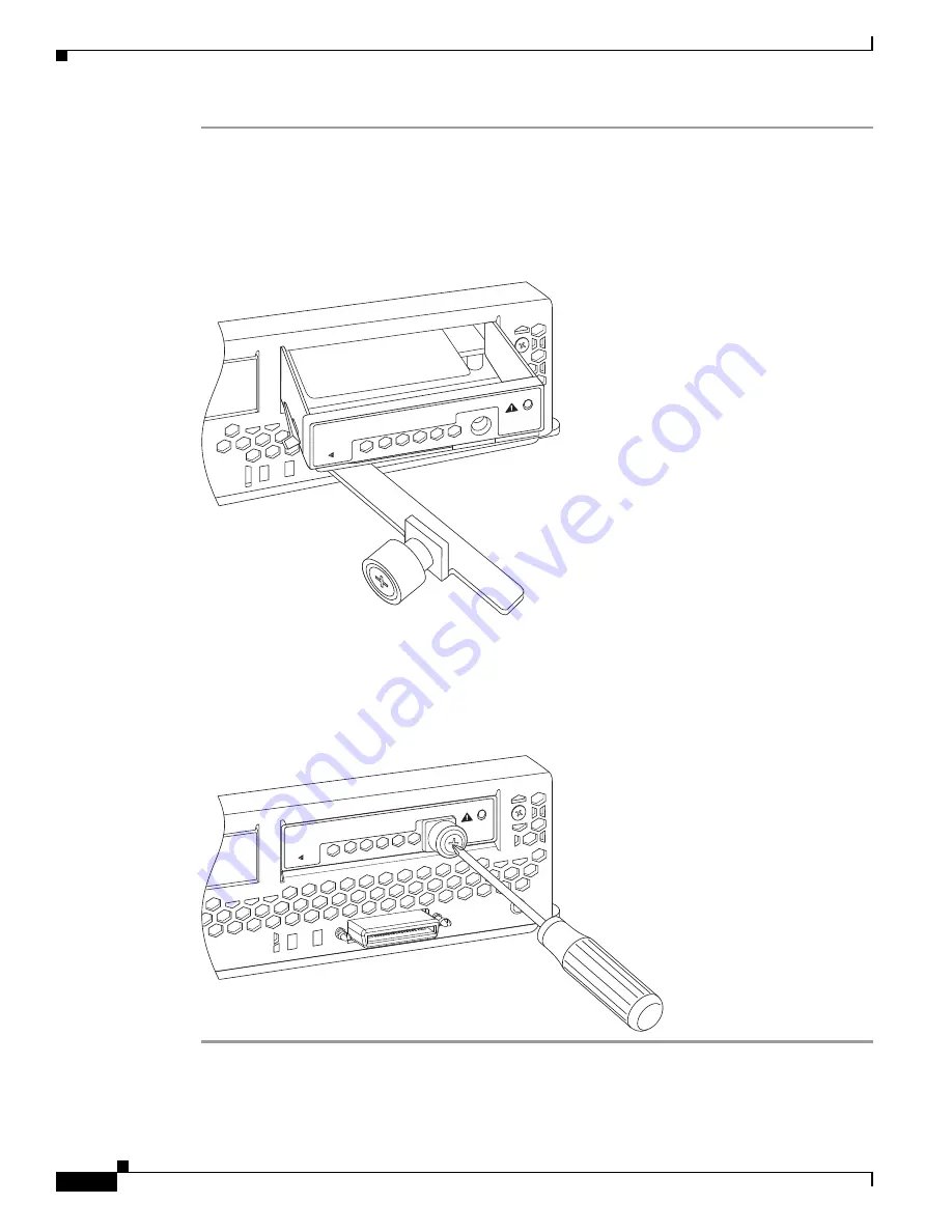
Slide the BBU unit in partially, and align the ejector lever as shown in 

Figure 18

Figure 18

Slide in the BBU 

.

Step 4

Continue pressing the BBU in until the ejector lever folds below the carrier tray. The BBU rear connector 
should automatically seat with the RAID controller at its rear.

Step 5

Secure the BBU in place by tightening the captive screw with a #2 Phillips screwdriver.

Figure 19

Tighten the Captive Screw

N20-LBBU

      REMOV

AL

SEE MANUAL

278829

N20-LBBU

      REMOV

A

L

SEE MANUAL

278830

Summary of Contents for UCS B440

Page 1: ... dual port adapter card connections for up to 40 Gbps of redundant I O throughput Industry standard double data rate 3 DDR3 memory supporting up to 32 DIMM slots and up to 256 GB of memory Remote management through an integrated service processor that also executes policy established in Cisco UCS Manager software Local keyboard video and mouse KVM access through a front console port on each server...

Page 2: ...e beaconing indication The removable hard disks also have LEDs indicating hard disk access activity and hard disk health 1 Hard drive bay 1 9 Right ejector thumbscrew 2 Hard drive bay 2 10 Power button and LED 3 Hard drive bay 3 11 Network link status LED 4 Hard drive bay 4 12 Blade health LED 5 RAID battery backup module BBU 13 Local console connection 6 Left ejector thumbscrew 14 Reset button ac...

Page 3: ...mount server is set to off using the power button or Cisco UCS Manager to reset the server will cause the desired power state of the server to become out of sync with the actual power state and the server may unexpected shutdown at a later time To safely reboot a server from a power down state use the Boot Server action in Cisco UCS Manager Connectors A console port is provided to give a direct co...

Page 4: ...ng on a blade server The pinout for the DB 9 connector is shown in Table 2 Figure 2 KVM Cable for Blade Servers Conventions This document uses the following conventions for notes cautions and safety warnings Notes and Cautions contain important information that you should know Note Means reader take note Notes contain helpful suggestions or references to material that are not covered in the public...

Page 5: ...lektrische schakelingen betrokken risico s en dient u op de hoogte te zijn van de standaard praktijken om ongelukken te voorkomen Gebruik het nummer van de verklaring onderaan de waarschuwing als u een vertaling van de waarschuwing die bij het apparaat wordt geleverd wilt raadplegen BEWAAR DEZE INSTRUCTIES Varoitus TÄRKEITÄ TURVALLISUUSOHJEITA Tämä varoitusmerkki merkitsee vaaraa Tilanne voi aiheu...

Page 6: ...INSTRUKSJONER Dette advarselssymbolet betyr fare Du er i en situasjon som kan føre til skade på person Før du begynner å arbeide med noe av utstyret må du være oppmerksom på farene forbundet med elektriske kretser og kjenne til standardprosedyrer for å forhindre ulykker Bruk nummeret i slutten av hver advarsel for å finne oversettelsen i de oversatte sikkerhetsadvarslene som fulgte med denne enhet...

Page 7: ...a varningssignal signalerar fara Du befinner dig i en situation som kan leda till personskada Innan du utför arbete på någon utrustning måste du vara medveten om farorna med elkretsar och känna till vanliga förfaranden för att förebygga olyckor Använd det nummer som finns i slutet av varje varning för att hitta dess översättning i de översatta säkerhetsvarningar som medföljer denna anordning SPARA...

Page 8: ... de prevenção de acidentes Use o número da declaração fornecido ao final de cada aviso para localizar sua tradução nos avisos de segurança traduzidos que acompanham o dispositivo GUARDE ESTAS INSTRUÇÕES Advarsel VIGTIGE SIKKERHEDSANVISNINGER Dette advarselssymbol betyder fare Du befinder dig i en situation med risiko for legemesbeskadigelse Før du begynder arbejde på udstyr skal du være opmærksom ...

Page 9: ...Se n d d o c u m e n t c o m m e n t s t o u c s d o c f e e d b a ck c i s c o c o m 9 Cisco UCS B440 High Performance Blade Server Installation and Service Note OL 22475 01 ...

Page 10: ...ons here to simplify the drawing Caution To prevent ESD damage wear grounding wrist straps during these procedures and handle modules by the carrier edges only Replacing an HDD or SSD with a drive of the same size model and manufacturer generally causes few problems with UCS Manager If the drive being replaced was part of a RAID array we recommend using a newly ordered drive of identical size mode...

Page 11: ...ely reinstalling it in another blade server Step 3 Install a blank faceplate N20 BBLKD to keep dust out of the blade server if the slot will remain empty Table 3 Supported Hard Disk Drives HDD Product ID Description A03 D073GC2 73 GB 6Gb SAS transfer rate 15K RPM HDD hot plug drive sled mounted A03 D146GC2 146 GB 6Gb SAS transfer rate 15k RPM SFF HDD hot plug drive sled mounted A03 D300GA2 300 GB ...

Page 12: ... install a blade server hard drive follow these steps Step 1 Place the hard drive lever into the open position by pushing the release button see Figure 3 Step 2 Gently slide the hard drive into the opening in the blade server until it seats into place Step 3 Push the hard drive lever into the closed position You can use UCS Manager to format and configure RAID services refer to the UCS Manager con...

Page 13: ...er establishing a connection to the blade server s operating system you can directly shut down the blade server using the operating system You can invoke a graceful shutdown or an emergency shutdown hard shutdown by using either of the following methods Use the UCS Manager See either the Cisco UCS Manager GUI Configuration Guide or the Cisco UCS Ma nager CLI Configuration Guide Use the Power butto...

Page 14: ...reinstalling it into another slot Step 6 If the slot is to remain empty reinstall the slot divider N20 CDIVV and install two blank faceplates N20 CBLKB1 to keep assure proper ventilation and cooling Installing a Cisco UCS B440 High Performance Blade Server While the blades and chassis are designed for any device to operate in any slot the following placement guidelines should be used when installi...

Page 15: ...Chassis Partition Step 2 Grasp the front of the blade server and place your other hand under the blade to support it See Figure 5 Figure 5 Positioning a Blade Server in the Chassis Step 3 Open the ejector levers in the front of the blade server Step 4 Gently slide the blade into the opening until you cannot push it any farther Step 5 Press the ejector levers so that they catch the edge of the chas...

Page 16: ...w on the front of the blade to no more than 3 in lbs Tightening with bare fingers only is unlikely to lead to stripped or damaged captive screws Removing a Blade Server Cover To open a blade server follow these steps Step 1 Press and hold the button down as shown in callout 1 of Figure 6 Step 2 While holding the back end of the cover pull the cover back and upas shown in callout 2 of Figure 6 Figu...

Page 17: ...ny failure notifications are sent to UCSM You can view these notification in the System Error Log or in the output of the show tech support command If errors are found an amber diagnostic LED will also light up next to the failed component During run time the blade BIOS component drivers and OS all monitor for hardware faults and will light up the amber diagnostic LED for a component if an uncorre...

Page 18: ... face of the HDD Faults on the CPU DIMMs or adapter cards will also cause the server health LED to light solid Amber for minor error conditions or blinking Amber for critical error conditions topicWorking Inside the Blade Server This section describes how to perform the following tasks within a blade server Installing a Motherboard CMOS Battery page 18 Removing a CPU or Heat Sink page 20 Installin...

Page 19: ... Lift the battery from the socket Use needle nose pliers to grasp the battery if there is not enough clearance for your fingers Step 2 Install a motherboard CMOS battery a Press the battery socket retaining clip toward the chassis wall b Insert the new battery into the socket with the battery s positive marking toward the chassis wall Ensure that the retaining clip clicks over the top of the batte...

Page 20: ...ep 2 Remove the heat sink N20 BHTS3 as shown in callout 2 of Figure 9 Remove the old thermal compound from the bottom of the heat sink using the cleaning kit UCSX HSCK available from Cisco Follow the instructions on the two bottles of cleaning solvent Step 3 Unhook the socket latch as shown in callout 3 of Figure 9 Step 4 Open the socket latch as shown in callout 4 of Figure 9 Step 5 Remove the CP...

Page 21: ...5 01 topicWorking Inside the Blade Server Figure 9 Removing the Heat Sink and Accessing the CPU Socket If a replacement CPU will not be used and the CPU will be left vacant you should have an air blocker installed rather than a heat sink The air blocker assures that air flows where it is needed and is shown in Figure 10 Figure 10 CPU Air Blocker 196873 1 4 5 3 1 2 278697 ...

Page 22: ...nk follow these steps Step 1 Place the CPU on the base with the notches aligned to the pins on the base See Figure 11 callout 1 Figure 11 Inserting the CPU and Replacing the Heat Sink Step 2 Close the socket latch See Figure 11 callout 2 Step 3 Lock the socket latch into place with the hook See Figure 11 callout 3 Step 4 Attach the thermal pad also available as a spare A04 BTHP3 provided with the ...

Page 23: ... Server Step 2 Press the DIMM into its slot evenly on both ends until it clicks into place refer to callout 2 in Figure 12 The DIMM connector latches will snap into place Note DIMMs are keyed and will only insert into their slot if the notch at the bottom of the DIMM is oriented correctly Attempting to force an incorrectly oriented DIMM will damage the slot Step 3 Press the DIMM connector latches ...

Page 24: ...t support third party memory DIMMs and in some cases their use may irreparably damage the server and require an RMA and down time Memory Arrangement The Cisco UCS B440 high performance blade server contains 32 slots for installing DIMMs 8 for each CPU Each CPU has 8 DIMM slots and DDR channels with 4 pairs of DIMMs operating in lockstep see Figure 13 so you must install additional DIMMs in pairs a...

Page 25: ...low black and white and Cisco recommends installing memory in that order It is also recommended to install memory evenly across the installed CPUs Figure 13 Memory Slots Within the Blade Server Channels Each CPU has 8 channels consisting of 4 matched pairs Each channel pair is identified by a letter A B C or D for each CPU Each channel pair member is identified by numbers either 1 or 0 Figure 14 s...

Page 26: ...a CPU will lead to memory errors Figure 14 Physical Representation of DIMMs for a CPU Figure 15 shows a logical view of the channels Figure 15 Logical Representation of Channels DIMMs can be used in the High performance blade server using the slot pairs described in Table 8 Memory Performance When configuring your server consider the following DIMMs within the blade server can be of a different si...

Page 27: ...nstallation process The following options are available If you are switching from one type of card to another before you physically perform the switch make sure you have downloaded the latest device drivers and loaded them into the server s OS For the most recent details refer to the firmware management chapter of one of the UCS Manager software configuration guides Table 9 Adapter Card Options Ci...

Page 28: ...allout 3 of Figure 16 Figure 16 Installing an Adapter Card Installing a RAID License Key Depending on the RAID license key that is installed the onboard RAID controller supports the following RAID levels RAID 0 data striping Data is striped across all disks in the array providing fast throughput There is no data redundancy and all data is lost if any disk fails RAID 1 disk mirroring Data is writte...

Page 29: ...t as the physical connector is different you must order replacements from Cisco User information for RAID controllers is in the Cisco UCS Servers RAID Guide To install a RAID license key follow these steps Step 1 With the cover removed locate the RAID controller daughter card It is directly behind the BBU Step 2 Align the key as shown and slide it onto the connector This should be very much like i...

Page 30: ... plate if present from the BBU bay at the right of the server Step 3 Slide the BBU unit in partially and align the ejector lever as shown in Figure 18 Figure 18 Slide in the BBU Step 4 Continue pressing the BBU in until the ejector lever folds below the carrier tray The BBU rear connector should automatically seat with the RAID controller at its rear Step 5 Secure the BBU in place by tightening th...

Page 31: ...Cisco technical documentation as an RSS feed and deliver content directly to your desktop using a reader application The RSS feeds are a free service Cisco and the Cisco logo are trademarks or registered trademarks of Cisco and or its affiliates in the U S and other countries To view a list of Cisco trademarks go to this URL www cisco com go trademarks Third party trademarks mentioned are the prop...

Page 32: ...Se n d d o c u m e n t c o m m e n t s t o u c s d o c f e e d b a ck c i s c o c o m 32 Cisco UCS B440 High Performance Blade Server Installation and Service Note OL 22475 01 Related Documentation ...

Reviews: