Chapter 2 Installing the Tap
42
4013399 Rev C
To Attach the Twisted Pair Cable
Follow these steps to attach the Twisted Pair cable.
1
Open the PDU access cover by loosening the 3/8-inch screws.
2
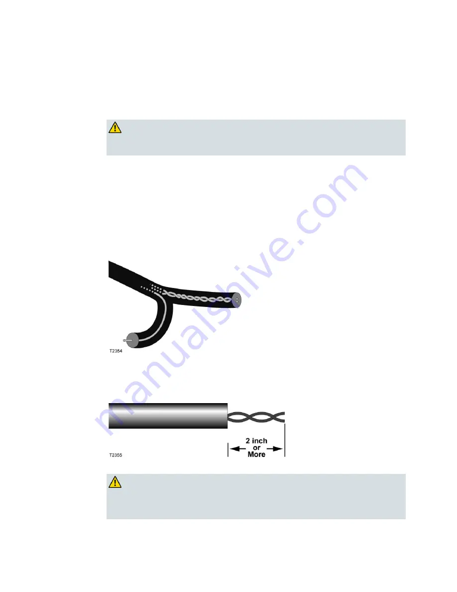
Carefully split the parallel wire to separate the twisted pair sheath from the coax
sheath.
CAUTION:
A twisted pair power installation requires that the cable be prepared to
properly mate with the twisted pair connectors.
You must use a utility knife or similar tool to cut the web close to the twisted
pair sheath without nicking the outer cover of the twisted pair or the coax.
Cut back the web a distance of 16 in. to 18 in. (40.6 cm to 45.7 cm), or
whatever is appropriate for your installation, so that the coax can gently bend
to connect to the drop F-ports and the twisted pair can enter at the bottom of
the PDU.
Ensure that the twisted pair sheath is prepared so that the outside of the
sheath is circular as shown in the following diagram (with any burred edges
removed).
3
Cut off approximately 2 inches (5.1cm) of the outer sheath so that the two
twisted pair wires are exposed.
Note
: The Twisted Pair PDU uses IDC connectors and does not require
insulation to be removed.
4
Lift the desired connector into the open position.
WARNING:
If installing the Twisted Pair PDU with PTCs installed (part numbers 750595
and 750596), avoid electrical shock. AC power is present on the IDCs during
installation.
Summary of Contents for Surge-Gap Multimedia Tap
Page 1: ...4013399 Rev C Surge Gap Multimedia Tap Installation and Operation Guide ...
Page 2: ......
Page 33: ...Preparing for Installation 4013399 Rev C 19 ...
Page 60: ......
Page 62: ...Chapter 3 Customer Support Information 48 4013399 Rev C ...
Page 70: ......
Page 73: ......


