background image


Chapter 2    Installing the Tap 


24 

4013399 Rev C 

5


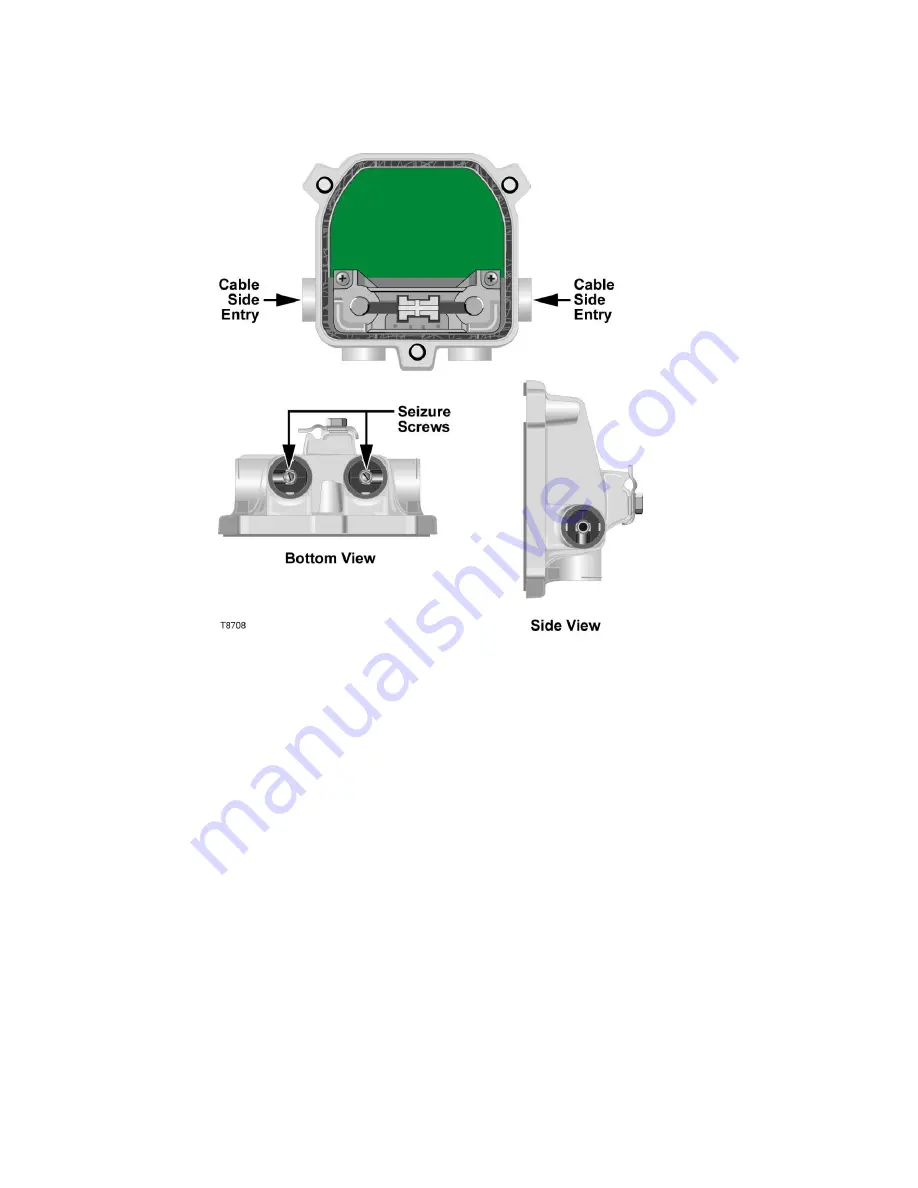
Using a 3/16-in. hex-head driver or 3/16-in. straight blade screwdriver, loosen 
the two seizure screws inside the housing. 


6


Thread the prepared KS-connectors into the housing at the cable side entry port 
locations as shown in the figure above.  Make sure to tighten the connector 
according to the manufacturer‟s recommended torque specification, typically 15 
ft-lb to 25 ft-lb (20.3 Nm to 33.9 Nm), but not to exceed 60 ft-lb (81.3 Nm). 

7


Using a 3/16-in. hex-head driver or 3/16-in. straight blade screwdriver, tighten 
the two seizure screws from 15 in-lb to 20 in-lb (1.7 Nm to 2.3 Nm). See the 
diagram in step 5 for the location of the two seizure screws. 

8


Replace the end plugs on the unused entry ports and torque with a 3/8-in. hex 
wrench from 50 in-lb to 60 in-lb (5.6 Nm to 6.8 Nm). 

9


Attach the faceplate to the housing. Refer to 

To Mount the Faceplate

 (on page 

27). 

10


Attach the drop cable (RG-6 or RG-59) to the tap faceplate. 

Important:

 For any drop cables that will have AC power activated, be sure that 

power blocking device(s) are installed at the home to prevent AC from passing to 
subscriber televisions, set-top converters, or FM receivers.  AC power must only 
be allowed to pass to the telephony equipment requiring it. 


Note:

  Be sure to provide strain relief for the coax drop cable per manufacturer‟s 

recommendation, and terminate all unused F-ports with 75 

 terminators. 


Summary of Contents for Surge-Gap Multimedia Tap

Page 1: ...4013399 Rev C Surge Gap Multimedia Tap Installation and Operation Guide ...

Page 2: ......

Page 3: ...f the flash points to the terminal device You may find this symbol affixed to the product This symbol indicates a protective ground terminal You may find this symbol affixed to the product This symbol indicates a chassis terminal normally used for equipotential bonding You may find this symbol affixed to the product This symbol warns of a potentially hot surface You may find this symbol affixed to...

Page 4: ... to change this publication at any time without notice This document is not to be construed as conferring by implication estoppel or otherwise any license or right under any copyright or patent whether or not the use of any information in this document employs an invention claimed in any existing or later issued patent Copyright 2006 2008 2012 Cisco and or its affiliates All rights reserved Printe...

Page 5: ...Surge Gap Multimedia Full Profile Tap with Coax PDU 11 2 4 8 way Surge Gap Multimedia Full Profile Tap with Twisted Pair PDU 12 Power Distribution Unit 13 Types of PDUs 13 Features of the PDU 13 2 4 way Coax PDU 14 2 4 way Twisted Pair PDU 14 Chapter 2 Installing the Tap 15 Tools and Torque Specifications 16 Tools Required 16 Torque Specifications 16 Torque Sequence 17 Preparing for Installation 1...

Page 6: ...ed Pair PDU 37 To Install the Twisted Pair PDU on a Strand Mounted Surge Gap Multimedia Tap 38 To Install the Twisted Pair PDU on a Pedestal Mounted Surge Gap Multimedia Tap 39 To Attach the Faceplate to the Housing 41 To Attach the Twisted Pair Cable 42 Chapter 3 Customer Support Information 47 Appendix A Technical Information 49 Specifications 50 Dimensions 50 Surge Gap Multimedia Taps Electrica...

Page 7: ...expected to use their experience and technical skills to avoid possible injury to themselves and others due to hazards that exist in service and restricted access areas User and Operator The terms user and operator apply to persons other than service personnel Ground ing and Earth ing The terms ground ing and earth ing are synonymous This document uses ground ing for clarity but it can be interpre...

Page 8: ... installation operation Ensure that the strand can safely support the equipment s weight Pedestal Service Closet Equipment Room or Underground Vault Installation WARNING Avoid the possibility of personal injury Ensure proper handling lifting techniques are employed when working in confined spaces with heavy equipment Ensure this equipment is securely fastened to the mounting surface or rack where ...

Page 9: ...fic installation instructions in this manual or in companion manuals in this series for connection to network ferro resonant AC power sources AC Power Shunts AC power shunts may be provided with this equipment Important The power shunts where provided must be removed before installing modules into a powered housing With the shunts removed power surge to the components and RF connectors is reduced ...

Page 10: ...grounded equipment rack Safety Plugs European Union Class I Mains Powered Equipment Provided with a 3 terminal AC inlet and requires connection to a 3 terminal mains supply outlet via a 3 terminal power cord for proper connection to the protective ground Note The equipotential bonding terminal provided on some equipment is not designed to function as a protective ground connection Class II Mains P...

Page 11: ...epair do not wear electrically conducting objects such as a wristwatch or jewelry Lightning Do not work on this equipment or connect or disconnect cables during periods of lightning Labels Do not remove any warning labels Replace damaged or illegible warning labels with new ones Covers Do not open the cover of this equipment and attempt service unless instructed to do so in the instructions Refer ...

Page 12: ...rectly inserted Do not attempt to recharge disposable or non reusable batteries Please follow instructions provided for charging rechargeable batteries Replace batteries with the same or equivalent type recommended by manufacturer Do not expose batteries to temperatures above 100 C 212 F Disposal The batteries may contain substances that could be harmful to the environment Recycle or dispose of ba...

Page 13: ...MC regulatory requirements Refer to this equipment s data sheet for details about regulatory compliance approvals EMC performance is dependent upon the use of correctly shielded cables of good quality for all external connections except the power source when installing this equipment Ensure compliance with cable connector specifications and associated installation instructions where given elsewher...

Page 14: ...with Canadian ICES 003 Cet appareil est confome à la norme NMB 003 du Canada CENELEC CISPR Statement with Respect to Class A Information Technology Equipment This is a Class A equipment In a domestic environment this equipment may cause radio interference in which case the user may be required to take adequate measures ...

Page 15: ...omplete the procedures described in this guide Cisco service engineers who help system operators manage their systems will also find the contents of this guide useful Qualified Personnel Only appropriately qualified and skilled personnel should attempt to install operate maintain and service this product WARNING Allow only qualified and skilled personnel to install operate maintain and service thi...

Page 16: ... way Surge Gap Multimedia Tap Standard Faceplate 7 2 4 8 way Surge Gap Multimedia Tap Full Profile Faceplate 8 2 4 way Surge Gap Multimedia Standard Tap with Coax PDU 9 2 4 way Surge Gap Multimedia Standard Tap with Twisted Pair PDU 10 2 4 8 way Surge Gap Multimedia Full Profile Tap with Coax PDU 11 2 4 8 way Surge Gap Multimedia Full Profile Tap with Twisted Pair PDU 12 Power Distribution Unit 13...

Page 17: ...p System provides enhanced reliability features that are essential to successful video and telephony service delivery Surge Gap Multimedia Tap System Diagrams The Surge Gap Multimedia Tap System consists of the Surge Gap Multimedia Tap faceplate and housing and the Power Distribution Unit PDU There are two types of PDUs coax power and twisted pair power Refer to Power Distribution Unit on page 13 ...

Page 18: ...tional taps However the Surge Gap Multimedia Tap offers a variety of enhanced features essential to the successful delivery of telephony and other advanced services The following are features of the Surge Gap Multimedia Tap Connection Beam AC RF bypass switch 12 amperes through current rating Power injection posts Economical two step upgrade to customer drop power passing capability AC blocking ca...

Page 19: ...2 4 way Surge Gap Multimedia Tap Standard Housing 4013399 Rev C 5 2 4 way Surge Gap Multimedia Tap Standard Housing The following illustration shows the 2 4 way Surge Gap Multimedia Tap standard housing ...

Page 20: ...ducing the Surge Gap Multimedia Tap System with PDU 6 4013399 Rev C 2 4 8 way Surge Gap Multimedia Tap Full Profile Housing The following illustration shows the 2 4 8 way Surge Gap Multimedia Tap full profile housing ...

Page 21: ...399 Rev C 7 2 4 way Surge Gap Multimedia Tap Standard Faceplate The following illustration shows the 4 way Surge Gap Multimedia Tap standard faceplate installed on the housing Note The 2 way version is identical except that F ports 3 and 4 are not installed ...

Page 22: ... Tap Full Profile Faceplate The following illustration shows the 8 way Surge Gap Multimedia Tap full profile faceplate installed on the housing Note The 2 way version is identical except that F ports 1 2 5 6 7 and 8 are not installed The 4 way version is identical except that F ports 1 6 7 and 8 are not installed ...

Page 23: ...3399 Rev C 9 2 4 way Surge Gap Multimedia Standard Tap with Coax PDU The following illustration shows the full view of the 4 way Surge Gap Multimedia Standard Tap with a Coax PDU Note The 2 way version is identical except that F ports 3 and 4 are not installed ...

Page 24: ...3399 Rev C 2 4 way Surge Gap Multimedia Standard Tap with Twisted Pair PDU The following illustration shows the full view of the 4 way Surge Gap Multimedia Standard Tap with a Twisted Pair PDU Note The 2 way version is identical except that F ports 3 and 4 are not installed ...

Page 25: ...ll Profile Tap with Coax PDU The following illustration shows the full view of the 8 way Surge Gap Multimedia Full Profile Tap with a Coax PDU Note The 2 way version is identical except that F ports 1 2 5 6 7 and 8 are not installed The 4 way version is identical except that F ports 1 6 7 and 8 are not installed ...

Page 26: ...ofile Tap with Twisted Pair PDU The following illustration shows the full view of the 8 way Surge Gap Multimedia Full Profile Tap with a Twisted Pair PDU Note The 2 way version is identical except that F ports 1 2 5 6 7 and 8 are not installed The 4 way version is identical except that F ports 1 6 7 and 8 are not installed ...

Page 27: ...e Both coax and twisted pair power versions are available in 2 4 way and 8 way versions Features of the PDU The following features of the PDU are available in 2 4 way and 2 4 8 way versions Available in twisted pair and coaxial drop powering versions Compatible with Cisco s Surge Gap Multimedia Tap Provides uninterrupted downstream subscriber service during tap faceplate removal Current limiting u...

Page 28: ... 2 4 way Coax PDU The following diagram shows the front and back view of the 2 4 way Coax PDU Note The 2 4 8 way coax PDU is similar 2 4 way Twisted Pair PDU The following diagram shows the front and back view of the 2 4 way Twisted Pair PDU Note The 2 4 8 way twisted pair is similar ...

Page 29: ...nstalling the Tap In This Chapter Tools and Torque Specifications 16 Preparing for Installation 18 Removing the Faceplate 20 Installing the Tap Housing on a Strand 23 Installing the Tap Housing in a Pedestal 25 Mounting the Faceplate 27 Installing the PDU 30 Installing the Coax PDU 32 Installing the Twisted Pair PDU 37 ...

Page 30: ...minimum 0 Nm to 28 2 Nm minimum Tighten seizure screws connectors and retainer bolts 7 16 in wrench Tighten house drop F connector 15 16 in 1 in and 1 1 8 in wrenches Tighten connectors for feeder cable Sizes may vary depending on manufacturer and connector style Grounding wire assembly part number 569533 hot install only Prevent electric shock and equipment damage Certain components can deliver a...

Page 31: ...b 5 6 Nm to 6 8 Nm Seizure screw 15 in lb to 20 in lb 1 7 Nm to 2 3 Nm Faceplate bolt 50 in lb to 60 in lb 5 6 Nm to 6 8 Nm F connector drop cable RG 6 or RG 59 Tighten to manufacturer s recommended torque specification Installations involving a twisted pair PDU also require tightening the PDU cover screw to 50 to 60 in lb 5 6 to 6 8 Nm Torque Sequence The following diagrams show the proper torque...

Page 32: ...while also allowing for expansion hoops in strand installations 2 Prepare the cable ends per the cable manufacturer s recommended method 3 Place the connector above the entry port so that it lines up with its installed position 4 If the pin extends past the stripline on the housing use wire cutters to trim the pin flush to the stripline See the diagram below for a visual guide WARNING Avoid electr...

Page 33: ...Preparing for Installation 4013399 Rev C 19 ...

Page 34: ...e procedure To Remove a Faceplate with Feeder Cables Connected Hot Install on page 21 To Remove the Faceplate Follow these steps to remove the tap faceplate from the housing 1 Using a 3 8 in wrench loosen all faceplate bolts as shown in the 4 way tap diagram below 2 Pull the faceplate straight out from the housing You need to use a small amount of force to pull the faceplate out CAUTION Handle the...

Page 35: ... wrench loosen all faceplate bolts 3 If the housing is installed on a strand go to step 4 If the housing is installed on a pedestal go to step 5 WARNING Protect yourself from electric shock and your equipment from damage Certain components can deliver an electrical shock 4 Attach a grounding wire assembly to the strand wire and a drop port F connector Proceed to step 6 5 Attach a grounding wire as...

Page 36: ...ew Back View Proceed to step 6 6 Pull the faceplate straight out from the housing You need to use a small amount of force to pull the faceplate out CAUTION Handle the faceplate with care to avoid damage to the circuitry mounted to the rear of the faceplate ...

Page 37: ...strand for mounting To Install the Tap Housing on a Strand Follow these steps to install a tap housing on a strand 1 Begin this procedure with the faceplate removed Refer to To Remove the Faceplate on page 20 2 Using a 3 8 in wrench loosen the strand clamp bolt 3 Attach the housing to the strand making sure that the strand enters the strand clamp 4 Secure the strand clamp to the strand by tighteni...

Page 38: ...lb 1 7 Nm to 2 3 Nm See the diagram in step 5 for the location of the two seizure screws 8 Replace the end plugs on the unused entry ports and torque with a 3 8 in hex wrench from 50 in lb to 60 in lb 5 6 Nm to 6 8 Nm 9 Attach the faceplate to the housing Refer to To Mount the Faceplate on page 27 10 Attach the drop cable RG 6 or RG 59 to the tap faceplate Important For any drop cables that will h...

Page 39: ... or filters are installed To Install the Tap Housing in a Pedestal Follow these steps to install a tap housing in a pedestal 1 Begin this procedure with the faceplate removed Refer to To Remove the Faceplate on page 20 2 Using a 3 8 in wrench remove the strand bolt and strand clamp from the housing 3 Mount the housing to the pedestal mounting bracket using the strand bolt Use the strand clamp as a...

Page 40: ...lb 1 7 Nm to 2 3 Nm See the diagram in step 5 for the location of the two seizure screws 8 Replace the end plugs on the unused entry ports and torque with a 3 8 in hex wrench from 50 in lb to 60 in lb 5 6 Nm to 6 8 Nm 9 Attach the faceplate to the housing Refer to To Mount the Faceplate on page 27 10 Attach the drop cable RG 6 or RG 59 to the tap faceplate Important For any drop cables that will h...

Page 41: ...the housing 1 If the housing is installed on a strand go to step 2 If the housing is installed in a pedestal go to step 3 WARNING Protect yourself from electric shock and your equipment from damage Certain components can deliver an electrical shock 2 Attach a grounding wire assembly to the strand wire and a drop port F connector Proceed to step 4 3 Attach a grounding wire assembly to the strand cl...

Page 42: ...iew Back View Proceed to step 4 4 Inspect the housing gasket and all mating surfaces Wipe off any dirt moisture or debris 5 Place the faceplate on the tap housing Push firmly on the faceplate to seat it in the housing 6 Remove the grounding wire assembly ...

Page 43: ...Mounting the Faceplate 4013399 Rev C 29 7 Using a 3 8 in wrench tighten the faceplate bolts from 50 in lb to 60 in lb 5 6 Nm to 6 8 Nm ...

Page 44: ...timedia Tap to allow subscriber drop powering capability The tap may be mounted on a strand or in a pedestal and the drop may be either coax or twisted pair Strand Mounting Configuration The Multimedia Tap with a PDU can be mounted in a strand aerial position Refer to the following diagrams for strand mounting configuration ...

Page 45: ...4013399 Rev C 31 Pedestal Mounting Configuration The Multimedia Tap with a PDU can be mounted on a pedestal Refer to the following diagram of a Multimedia Tap with a PDU for the recommended pedestal mounting configuration ...

Page 46: ...portant to perform this step now in order to prevent unwanted AC power transmission on a subscriber drop during installation 2 Using a 3 8 in wrench remove the faceplate from the existing tap by loosening the 3 8 in faceplate bolts See Removing the Faceplate on page 20 3 Remove the longer faceplate bolts attached to the plastic protective cover of the PDU Replace the shorter bolts removed from the...

Page 47: ...Coax PDU on a Strand Mounted Surge Gap Multimedia Tap Follow these steps to install the Coax PDU on a strand mounted tap 1 Attach the grounding wire assembly to the strand wire and the nearest PDU bolt clearance hole Refer to the following diagrams in this step for the location of the grounding wire assembly WARNING Protect yourself from electric shock and your equipment from damage Certain compon...

Page 48: ...ng on page 35 To Install the Coax PDU on a Pedestal Mounted Surge Gap Multimedia Tap Follow these steps to install the Coax PDU on a pedestal mounted tap 1 Attach the grounding wire assembly to the strand clamp bolt and the nearest PDU bolt clearance hole Refer to the following diagrams WARNING Protect yourself from electric shock and your equipment from damage Certain components can deliver an el...

Page 49: ... this end to the faceplate drop port F connector 4 Proceed to To Attach the Faceplate to the Housing on page 35 ToAttach the Faceplate to the Housing Follow these steps to install the faceplate to the housing 1 Carefully install the tap faceplate to the front of the PDU Using the longer faceplate bolts tighten the 3 8 in faceplate bolts from 50 in lb to 60 in lb 5 6 Nm to 6 8 Nm ...

Page 50: ...bly 3 On the desired port turn the switch from the OFF to ON position using a flat bladed screwdriver The switches are marked with the port numbers WARNING Please use extreme caution when turning the switch ON and OFF to prevent unwanted AC power transmission on a subscriber loop ...

Page 51: ...sted pair version without PTCs installed do not insert the PTCs before you begin your installation procedures This will result in AC power transmission on the subscriber drop during installation 1 Using a 3 8 in wrench remove the faceplate from the existing tap by loosening the 3 8 in faceplate bolts Refer to To Remove the Faceplate on page 20 2 Remove the longer faceplate bolts attached to the pl...

Page 52: ...sted Pair PDU on a Strand Mounted Surge Gap Multimedia Tap Follow these steps to install the Twisted Pair PDU on a strand mounted tap 1 Attach the grounding wire assembly to the strand wire and the nearest PDU access cover bolt Refer to the following diagram for the location of the grounding wire assembly WARNING Protect yourself from electric shock and your equipment from damage Certain component...

Page 53: ...5 To Install the Twisted Pair PDU on a Pedestal Mounted Surge Gap Multimedia Tap Follow these steps to install the Twisted Pair PDU on a pedestal mounted tap 1 Attach the grounding wire assembly to the strand clamp bolt and the nearest PDU access cover bolt Refer to the following diagrams WARNING Protect yourself from electric shock and your equipment from damage Certain components can deliver an ...

Page 54: ...Chapter 2 Installing the Tap 40 4013399 Rev C Front View Back View 2 Push the Twisted Pair PDU onto the back housing of the tap Refer to the illustration in step 3 ...

Page 55: ... faceplate to the housing 1 Carefully install the tap faceplate to the front of the PDU Using the longer faceplate bolts tighten the 3 8 in faceplate bolts from 50 in lb to 60 in lb 5 6 Nm to 6 8 Nm 2 Remove the grounding wire assembly 3 On the desired port turn the switch from the OFF to ON position using a flat bladed screwdriver The switches are marked with the port numbers WARNING Please use e...

Page 56: ...istance of 16 in to 18 in 40 6 cm to 45 7 cm or whatever is appropriate for your installation so that the coax can gently bend to connect to the drop F ports and the twisted pair can enter at the bottom of the PDU Ensure that the twisted pair sheath is prepared so that the outside of the sheath is circular as shown in the following diagram with any burred edges removed 3 Cut off approximately 2 in...

Page 57: ...revent unwanted AC power transmission on the twisted pair 5 Simultaneously push the ends of the two twisted pair wires through the small holes and into the respective hot and ground connectors Note The connector is labeled HOT and GND 6 Press down on the IDC connector until it is fully seated 7 Continue with additional twisted pair connections if necessary and then proceed to the next step ...

Page 58: ...ollows Stainless steel Halar fluorocarbon ECTFE Tefzel fluorocarbon ETFE High density polyethylene Weather resistant polypropylene 9 If installing PTCs proceed to step 10 If PTCs are already installed part numbers 750595 and 750596 proceed to step 12 10 On the desired port insert PTC part number 592049 into the appropriate PTC guide slot as shown WARNING Avoid electrical shock AC power is present ...

Page 59: ...er screws from 50 in lb to 60 in lb 5 6 Nm to 6 8 Nm 13 Attach the coax cable to the tap s drop F ports as desired Make sure to tighten according to the manufacturer s recommended torque specification Note Provide strain relief for the coax drop cable per manufacturer s recommendation 14 Install 75 terminators on all unused ports of the faceplate CAUTION Avoid damage to this product Before install...

Page 60: ......

Page 61: ...u options to speak with a service engineer Access your company s extranet site to view or order additional technical publications For accessing instructions contact the representative who handles your account Check your extranet site often as the information is updated frequently 3 Chapter 3 Customer Support Information ...

Page 62: ...Chapter 3 Customer Support Information 48 4013399 Rev C ...

Page 63: ...n Knowledge of product specifications and cable connectors can assist you in configuring the Surge Gap Multimedia Tap in your HFC network Scope This appendix covers important technical aspects of the Surge Gap Multimedia Tap System In This Appendix Specifications 50 Part Numbers 52 ...

Page 64: ...5 25 in W x 3 in D 107 95 mm H x 133 35 mm W x 76 2 mm D Twisted Pair PDU 4 way 5 2 in H x 3 83 in W x 3 in D 132 1 mm H x 97 3 mm W x 76 2 mm D Twisted Pair PDU 8 way 5 93 in H x 5 62 in W x 3 in D 150 6 mm H x 142 7 mm W x 76 2 mm D Coax PDU 4 way 3 7 in H x 3 8 in W x 1 81 in D 19 3 mm H x 97 8 mm W x 46 mm D Coax PDU 8 way 4 46 in H x 5 64 in W x 1 52 in D 113 3 mm H x 143 3 mm W x 38 73 mm D ...

Page 65: ...rge Gap Multimedia Tap 2 4 way and 2 4 8 way AL360T housing with powder coating for superior environmental protection Sealed and swaged extended F ports for maximum resistance to moisture ingress Tin plated brass F ports to ensure a corrosion resistant drop interface Component covers for additional protection of faceplate circuitry during maintenance Versatile housing design permits aerial pedesta...

Page 66: ...y 20 dB 753375 Surge Gap Tap 2 way 23 dB 753376 Surge Gap Tap 2 way 26 dB 753377 Surge Gap Tap 2 way 29 dB 753378 Surge Gap Tap 4 way 8 dB 753379 Surge Gap Tap 4 way 11 dB 753380 Surge Gap Tap 4 way 14 dB 753381 Surge Gap Tap 4 way 17 dB 753382 Surge Gap Tap 4 way 20 dB 753383 Surge Gap Tap 4 way 23 dB 753384 Surge Gap Tap 4 way 26 dB 753385 Surge Gap Tap 4 way 29 dB 753386 Standard Tap Surge Gap ...

Page 67: ...ate 4 way 26 dB 753409 Surge Gap Faceplate 4 way 29 dB 753410 Full Profile Taps Description Part Number Surge Gap Tap 2 way 4 dB 753418 Surge Gap Tap 2 way 8 dB 753419 Surge Gap Tap 2 way 11 dB 753420 Surge Gap Tap 2 way 14 dB 753421 Surge Gap Tap 2 way 17 dB 753422 Surge Gap Tap 2 way 20 dB 753423 Surge Gap Tap 2 way 23 dB 753424 Surge Gap Tap 2 way 26 dB 753425 Surge Gap Tap 2 way 29 dB 753426 S...

Page 68: ...y 14 dB 753438 Surge Gap Faceplate 2 way 17 dB 753439 Surge Gap Faceplate 2 way 20 dB 753440 Surge Gap Faceplate 2 way 23 dB 753441 Surge Gap Faceplate 2 way 26 dB 753442 Surge Gap Faceplate 2 way 29 dB 753443 Surge Gap Faceplate 4 way 8 dB 753444 Surge Gap Faceplate 4 way 11 dB 753445 Surge Gap Faceplate 4 way 14 dB 753446 Surge Gap Faceplate 4 way 17 dB 753447 Surge Gap Faceplate 4 way 20 dB 753...

Page 69: ... the PDUs Description Part Number 2 4 way coaxial drop powering 738447 8 way coaxial drop powering 738448 2 4 way twisted pair powering 738445 8 way twisted pair powering 738446 2 4 way twisted pair powering with PTCs installed 750595 8 way twisted pair powering with PTCs installed 750596 PTC Assemblies 1 bag of 100 592049 PTC Assembly required for use with the Twisted Pair PDU sold separately ...

Page 70: ......

Page 71: ... Pair PDU 37 Introducing the Surge Gap Multimedia Tap System with PDU 1 M Mechanical 51 Mounting the Faceplate 27 P Part Numbers 52 PDU Electrical 51 PDUs 55 Pedestal Mounting Configuration 31 Power Distribution Unit 13 Preparing for Installation 18 R Removing the Faceplate 20 S Specifications 50 Strand Mounting Configuration 30 Surge Gap Multimedia Tap System Diagrams 3 Surge Gap Multimedia Taps ...

Page 72: ...Index 58 4013399 Rev C Tools Required 16 Torque Sequence 17 Torque Specifications 16 Types of PDUs 13 ...

Page 73: ......

Page 74: ...various trademarks of Cisco Systems Inc Please see the Notices section of this document for a list of the Cisco Systems Inc trademarks used in this document Product and service availability are subject to change without notice 2006 2008 2012 Cisco and or its affiliates All rights reserved May 2012 Printed in USA Part Number 4013399 Rev C ...

Reviews: