8-9
Installation and Upgrade Guide for Cisco Secure Access Control System 5.6
Chapter 8 Installing the Cisco SNS 3415 and Cisco SNS 3495 Hardware Appliances
Connecting Cables
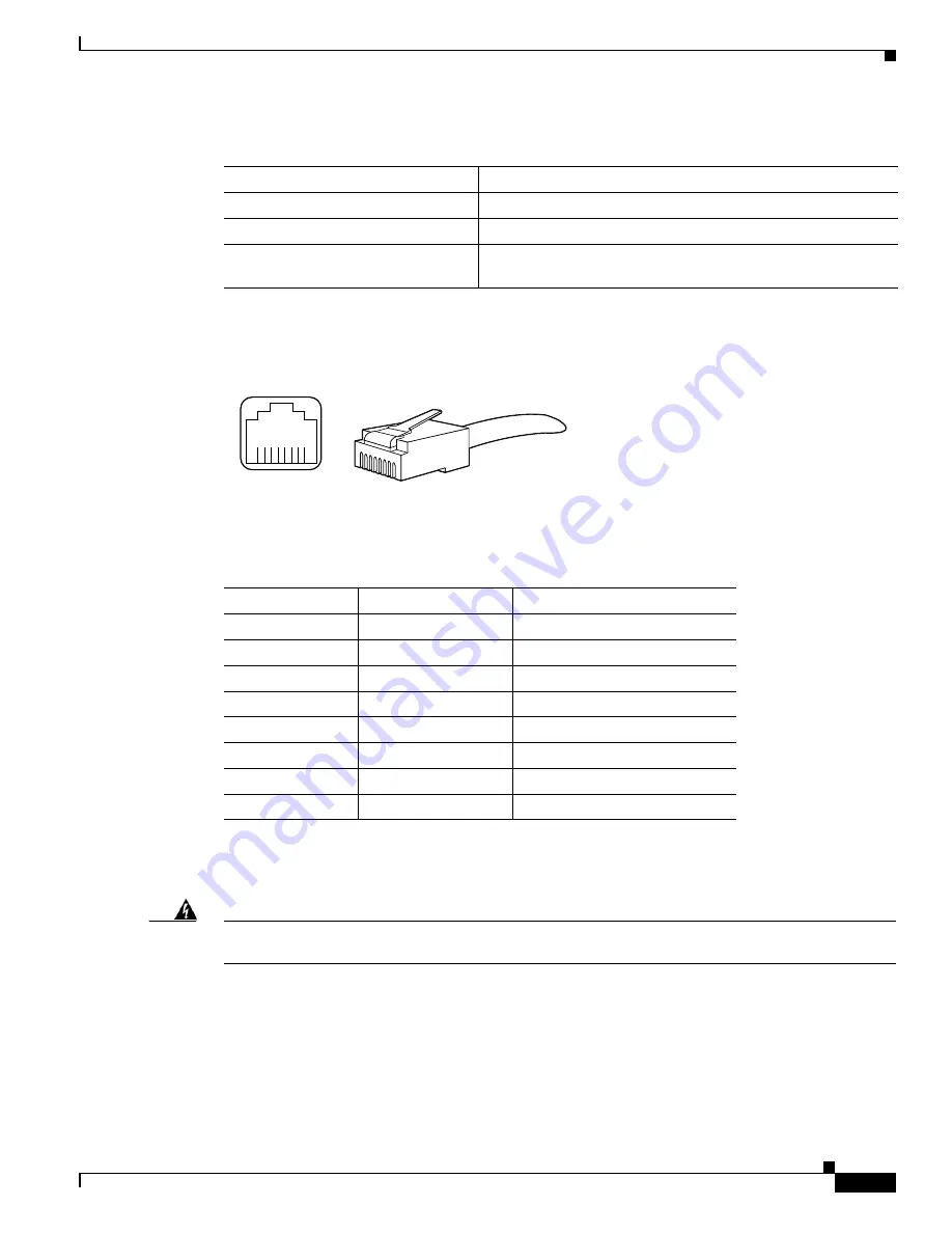
Figure 8-4
shows the Ethernet RJ-45 port and plug.
Figure 8-4
RJ-45 Port and Plug
Table 8-2
lists and describes the RJ-45 pin signals used on the connector.
Connecting the Console
Warning
Do not work on the system or connect or disconnect cables during periods of lightning activity.
Statement 1001
Your Cisco SNS-3415 or Cisco SNS-3495 appliance has a DCE-mode console port for connecting a
console terminal to your appliance. The appliance uses a DB-9 serial connector for the console port.
The console port on the Cisco SNS-3415 or Cisco SNS-3495 appliance includes an EIA/TIA-232
asynchronous serial (DB-9) connector. This serial console connector (port) allows you to access the
appliance locally by connecting a terminal—either a PC running terminal-emulation software or an
ASCII terminal—to the console port.
Table 8-1
Ethernet Cabling Guidelines
Type
Description
10BASE-T
EIA Categories 3, 4, or 5 UTP (2 or 4 pair) up to 328 ft (100 m)
100BASE-TX
EIA Category 5 UTP (2 pair) up to 328 ft (100 m)
1000BASE-T
EIA Category 6 UTP (recommended), Category 5E UTP or
5 UTP (2 pair) up to 328 ft (100 m)
210222
8 7 6 5 4
3
2 1
RJ-45 connector
Table 8-2
Ethernet Port Pinout
Ethernet Port Pin
Signal
Description
1
TxD+
Transmit data +
2
TxD–
Transmit data –
3
RxD+
Receive data +
4
Termination network
No connection
5
Termination network
No connection
6
RxD–
Receive data –
7
Termination network
No connection
8
Termination network
No connection


