Cisco VC 240 Network Camera Quick Start Guide
5
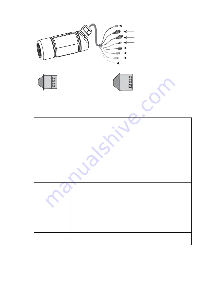
Back Panel
Ethernet LEDs
The green and amber Ethernet LEDs indicate status.
If powered using PoE:
• Green steady, amber steady
—Power on.
• Green blinking, amber steady
—Power on with
Ethernet data activity.
If powered using an external power adapter:
• Green steady, amber off
—Power on.
• Green blinking, amber off
—Power on with Ethernet
data activity.
General
Purpose Input/
Output (GPIO)
Allows you to connect the camera to external input/
output devices that can provide additional controlling
functions.
For more information, see the
Cisco VC240 Outdoor
WDR Day/Night PoE Network Camera Administration
Guide
found at:
http://www.cisco.com/en/US/products/ps9944/
prod_maintenance_guides_list.html
5-Port
Connector
Connects the camera to 24 VAC power (0.5 A) or serves
as an RS-485 port.
Ethernet 10/100 RJ45 Plug
Audio Out (green)
Microphone In (pink)
Power Cord Socket (black)
GPIO
5-Port Connector
Ground
Ethernet LEDs
198300
N.C.
485B
485A
AC24V
AC24V
GND
DI
DO
+12V
GND:
DI:
DO:
+12V:
GPIO
5-Port Connector
Ground
Digital Input
Digital Output
Power (12VDC)
NC:
485B:
485A:
AC24V:
AC24V:
No Connector
RS485-
RS485+
Power (24VAC)
Power (24VAC)


