background image


Chapter 2    Installing the Residential Gateway 


16 

4038767 Rev A 

4


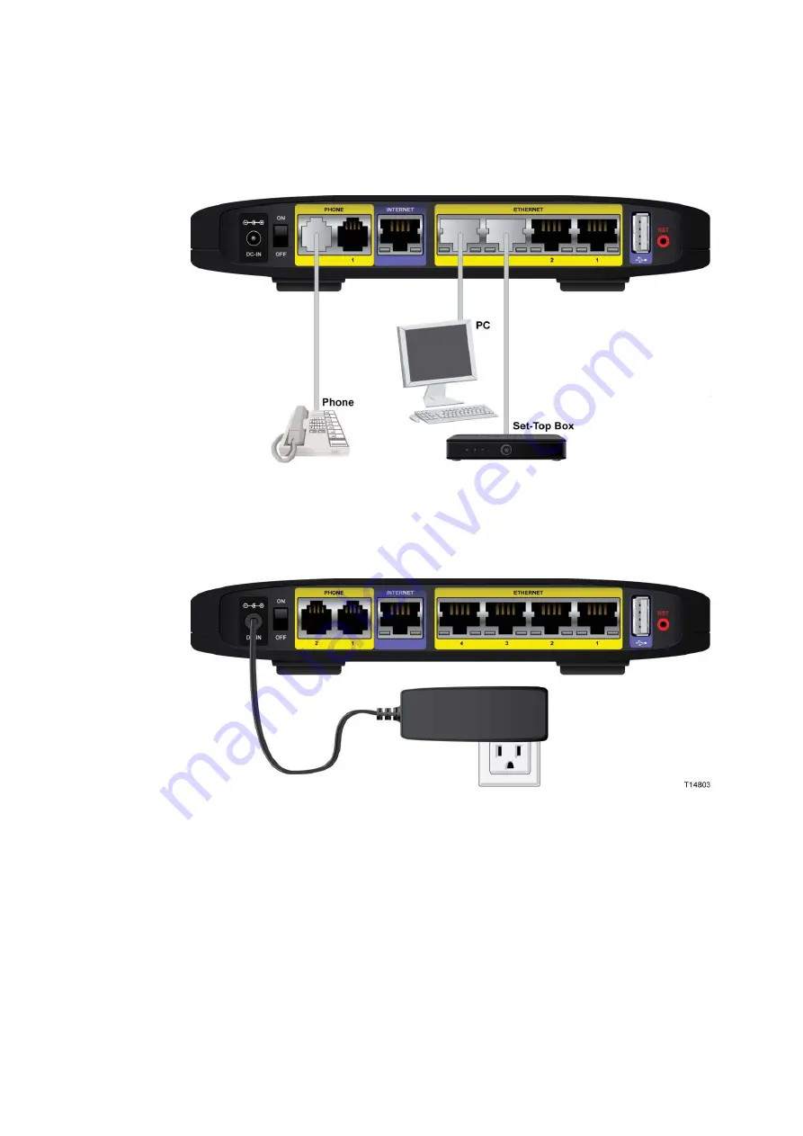
(Optional) Connect a PC or other Ethernet device to an ETHERNET port using a 
standard RJ-45 Ethernet cable. 


5


Connect the included power adapter to the residential gateway power port, and 
then plug the power adapter into an electrical outlet. The power LED on the 
front panel will light up as soon as the device powers on. 


6


Power on the residential gateway. The LCD will light up with a message that the 
device is booting up.  

Summary of Contents for REN301

Page 1: ...4038767 Rev A Cisco Managed Services Residential Gateway User Guide ...

Page 2: ......

Page 3: ...Please Read Important Please read this entire guide If this guide provides installation or operation instructions give particular attention to all safety statements included in this guide ...

Page 4: ...on many factors conditions and variables including distance from the access point volume of network traffic building materials and construction operating system used mix of wireless products used interference and other adverse conditions Publication Disclaimer Cisco Systems Inc assumes no responsibility for errors or omissions that may appear in this publication We reserve the right to change this...

Page 5: ...ent au personnel technique qualifié Pour réduire les risques de chocs électriques n effectuer aucune intervention autre que celles décrites dans le mode d emploi et les instructions relatives au fonctionnement à moins que vous ne soyez qualifié pour ce faire Mitteilung für CATV Techniker Die in dieser Mitteilung aufgeführten Wartungsanweisungen sind ausschließlich für qualifiziertes Fachpersonal b...

Page 6: ...uso exclusivo por parte de personal de mantenimiento cualificado Con el fin de reducir el riesgo de descarga eléctrica no realice ninguna otra operación de reparación distinta a las contenidas en las instrucciones de funcionamiento a menos que posea la cualificación necesaria para hacerlo 20080814_Installer800_Intl ...

Page 7: ...e and Foreign Objects viii Service Warnings ix Check Product Safety ix Protect the Product When Moving It ix Telephone Equipment Notice ix United States FCC Compliance xii Declaration of Conformity xii Canada EMI Regulation xii RF Exposure Statements xiii CE Compliance xvi Declaration of Conformity with Regard to the EU Directive 1999 5 EC R TTE Directive xvi National Restrictions xvii Antennas xv...

Page 8: ...2 Mounting the Residential Gateway Horizontally 12 Mounting the Residential Gateway Vertically 12 Connecting the Residential Gateway 15 Chapter 3 Configuration and Operation of the the Residential Gateway 19 Logging into the Residential Gateway 20 Internet 21 VoIP Settings 25 SIP 25 Service 26 Voice 28 Advanced 29 Call Log 30 Wi Fi 32 Home Address 34 Media Storage 35 Chapter 4 Using the LCD 37 Get...

Page 9: ... 53 Use Network Tools 55 View Router Information 57 Select LCD Display Orientation 58 View System Event Log 59 Set Up Time of Day Parameters 60 Chapter 5 Customer Information 63 Customer Support 64 If You Have Questions 64 Additional Information 65 Return Products for Repair 66 ...

Page 10: ......

Page 11: ... with the cart stand tripod bracket or table specified by the manufacturer or sold with the apparatus When a cart is used use caution when moving the cart apparatus combination to avoid injury from tip over 13 Unplug this apparatus during lightning storms or when unused for long periods of time 14 Refer all servicing to qualified service personnel Servicing is required when the apparatus has been ...

Page 12: ...o not place this apparatus on a bed sofa rug or similar surface Do not place this apparatus on an unstable surface Do not install this apparatus in an enclosure such as a bookcase or rack unless the installation provides proper ventilation Do not place entertainment devices such as VCRs or DVDs lamps books vases with liquids or other objects on top of this product Do not block ventilation openings...

Page 13: ...ing the apparatus or connecting or disconnecting cables Telephone Equipment Notice When using your telephone equipment basic safety precautions should always be followed to reduce the risk of fire electric stock and injury to persons including the following 1 Do not use this product near water for example near a bath tub wash bowl kitchen sink or laundry tub in a wet basement or near a swimming po...

Page 14: ......

Page 15: ...IMPORTANT SAFETY INSTRUCTIONS 4038767 Rev A xi ...

Page 16: ... television technician for help Any changes or modifications not expressly approved by Cisco Systems Inc could void the user s authority to operate the equipment The information shown in the FCC Declaration of Conformity paragraph below is a requirement of the FCC and is intended to supply you with information regarding the FCC approval of this device The phone numbers listed are for FCC related q...

Page 17: ...r RSS 102 Rev 4 The minimum separation distance from the antenna to general bystander is 7 9 inches 20 cm to maintain compliance EU This system has been evaluated for RF exposure for humans in reference to the ICNIRP International Commission on Non Ionizing Radiation Protection limits The evaluation was based on the EN 50385 Product Standard to Demonstrate Compliance of Radio Base Stations and Fix...

Page 18: ...uillage préjudiciable et 2 ce dispositif doit accepter tout brouillage reçu y compris un brouillage susceptible de provoquer un fonctionnement indésirable IMPORTANT NOTE Radiation Exposure Statement This equipment complies with IC radiation exposure limits set forth for an uncontrolled environment This equipment should be installed and operated with minimum distance 20cm between the radiator your ...

Page 19: ...United States FCC Compliance 4038767 Rev A xv ...

Page 20: ...ctive This declaration is only valid for configurations combinations of software firmware and hardware supported or provided by Cisco Systems for use within the EU The use of software or firmware not supported or provided by Cisco Systems may result in the equipment no longer being compliant with the regulatory requirements ...

Page 21: ...dans d autres parties de la bande 2 4 GHz Consultez http www arcep fr pour de plus amples détails Italy This product meets the National Radio Interface and the requirements specified in the National Frequency Allocation Table for Italy Unless this wireless LAN product is operating within the boundaries of the owner s property its use requires a general authorization Please check http www comunicaz...

Page 22: ...CE Compliance xviii 4038767 Rev A Antennas Use only the antenna supplied with the product 20090312 CE_Gateway ...

Page 23: ... Services Residential Gateway with ZigBee TES301Z Managed Services Residential Gateway with ZigBee with SIP TEI301Z Managed Services Residential Gateway with ZigBee with SIP IMS Audience This document is written for residential subscribers using a Managed Services Residential Gateway Related Publications Visit our website https www sciatl com subscriberextranet techpubs to view additional publicat...

Page 24: ...About This Guide xx 4038767 Rev A ...

Page 25: ...olution for Connected Home and Managed Home experiences This chapter lists the benefits and features of the residential gateway Illustrations and descriptions of the connection ports power and reset buttons touch sensitive keys and LED indicators are also provided 1 Chapter 1 Introducing the Managed Services Residential Gateway In This Chapter Benefits and Features 2 What s on the Top Panel 5 What...

Page 26: ...A Remote notifications for event triggering applications Optional IPSec for tunneling data to remote Storage servers Optional DTCP IP security for copyright protected music and video files Simplified Connected Home Easy to use and follow color LCD combined with Embedded Network Management to simplify connections configurations settings of IP devices in the home Supports remote management proactive...

Page 27: ...cteristics for this low power wireless technology used by home control monitoring and security include RF Frequency band Sub GHz Mesh Networking Every node is a repeater and self healing 32 bit unique identifier as Home ID to separate Z wave networks An 8 bit identifier called the Node ID is used to address individual nodes in the same network One Z wave network can have up to 232 nodes The REN301...

Page 28: ... DLNA UPnP and OSGi JVM friendly Remote Management via TR 069 TR 104 and embedded Network Management Home Energy Management Home Area Network HAN and an energy management service which enables more optimal use of energy by consumers Simplified Support Setup Embedded Network Management and Provisioning tool simplifies installation of the residential gateway Network Manager a PC based application th...

Page 29: ...ration Use the touch sensitive arrow keys to navigate through the menu options Refer to Configuration and Operation of the the Residential Gateway on page 19 for more information on this feature The top panel also provides LED status icons that indicate the operational state of your gateway Refer to the following diagram for a description of the top panel ...

Page 30: ...for 3 seconds to initiate pairing with Wi Fi devices 3 LCD with Touch Sensitive Keys LCD screen lights up by the wave of a hand to display menu options for common setup and configuration functions The touch sensitive keys indicated by the up down left and right arrows help you navigate through the menus 4 Phone 1 2 Blue The LED lights up blue when it is registered with SIP server It flashes to ind...

Page 31: ...e 1 2 The Phone ports connect standard analog telephones to the device 4 Internet The Internet port connects to the Ethernet port on the DSL fiber or cable modem 5 Ethernet LAN 1 4 These Ethernet ports 1 2 3 4 connect device to wired computers and other Ethernet network devices 6 USB The USB port connects to a USB storage device such as a USB hard drive or flash disk 7 Reset The Reset button resto...

Page 32: ...038767 Rev A What s on the Side Panel The side panel of your residential gateway provides an additional USB port Refer to the following diagram for a description of the back panel USB The USB port connects to a USB storage device such as a USB hard drive or flash disk ...

Page 33: ...Bottom Panel The bottom panel of your residential gateway provides holes for mounting screws for wall mounting and protective feet for vertical or wall mounting surfaces The factory label on the bottom panel provides serial number and MAC Address information ...

Page 34: ......

Page 35: ...troduction This chapter provides instructions for installing the residential gateway 2 Chapter 2 Installing the Residential Gateway In This Chapter Mounting the Residential Gateway 12 Connecting the Residential Gateway 15 ...

Page 36: ...al gateway has four rubber feet on its bottom panel Place the residential gateway on a level surface near an electrical outlet Mounting the Residential Gateway Vertically The residential gateway has four wall mount slots on its bottom panel The distance between two adjacent slots is 4 inches 101 6 mm Two screws are needed to mount the residential gateway ...

Page 37: ...ions of the wall mounting slots on the bottom of the residential gateway Use the information on this page as a guide for mounting your residential gateway to the wall Notes Mounting hardware illustrations are not true to scale Cisco is not responsible for damages incurred by insecure wall mounting hardware ...

Page 38: ...ion is within reach of an electrical outlet 2 Drill two holes into the wall Make sure the holes are 4 inches 101 6 mm apart 3 Insert a screw into each hole and leave 2 mm 0 8 inches below the head exposed 4 Maneuver the residential gateway so two of the wall mount slots line up with the two screws 5 Place the wall mount slots over the screws and slide the residential gateway down until the screws ...

Page 39: ...o an xDSL cable modem or other Internet device 2 Insert a standard RJ 11 telephone cable into the PHONE 1 port and connect the other end to an analog touchtone telephone 3 Optional You can connect the PHONE 2 port to a second analog telephone or a fax machine Note To prevent an invalid connection to the circuit switched Telco network do not connect an RJ 11 telephone cable from the PHONE 1 or PHON...

Page 40: ...tandard RJ 45 Ethernet cable 5 Connect the included power adapter to the residential gateway power port and then plug the power adapter into an electrical outlet The power LED on the front panel will light up as soon as the device powers on 6 Power on the residential gateway The LCD will light up with a message that the device is booting up ...

Page 41: ...or laptop to activate the wireless connection Note A wireless connection requires a wireless enabled notebook or a computer with an 802 11b g n wireless network adapter installed 8 Continue with the Configuration and Operation of the the Residential Gateway on page 19 chapter to configure your residential gateway ...

Page 42: ......

Page 43: ... based utility to set up connections and configure the residential gateway features 3 Chapter 3 Configuration and Operation of the the Residential Gateway In This Chapter Logging into the Residential Gateway 20 Internet 21 VoIP Settings 25 Wi Fi 32 Home Address 34 Media Storage 35 ...

Page 44: ...rovider for the login information 1 Launch the web browser on your computer 2 Type 192 168 29 1 in the URL Address field This value is the residential gateway s default IP address 3 Press Enter A login screen appears 4 Is this the first time you have opened the web based utility If yes type admin in the User name and Password fields If no enter the user name and password you established previously...

Page 45: ...Internet connection Your selection will determine which additional parameters will be required to complete your configuration Complete the following steps to set up your Internet connection 1 From the residential gateway dashboard click the Change Connection Type button located in the Internet cell ...

Page 46: ...value in the 1200 to 1500 range The default MTU is configured automatically For a Static connection Note Your service provider may provide static Internet IP address subnet mask and default gateway values Internet IP Address Enter the Gateway s IP address as seen from the Internet Subnet Mask Enter the Gateway s Subnet Mask as seen from the Internet including your service provider Default Gateway ...

Page 47: ... Connect on Demand You can configure the Router to cut the Internet connection after it has been inactive for a specified period of time Max Idle Time If your Internet connection has been terminated due to inactivity Connect on Demand enables the Router to automatically re establish your connection as soon as you attempt to access the Internet again Max Idle Time Enter the number of minutes you wa...

Page 48: ...Chapter 3 Configuration and Operation of the the Residential Gateway 24 4038767 Rev A 4 Click Save Changes to save the information or Cancel to return to the dashboard ...

Page 49: ...ttings SIP Complete the following steps to configure the SIP parameters for your VoIP settings 1 From the residential gateway dashboard click the Change Settings button located in the VoIP Settings cell 2 Complete the fields for the SIP tab ...

Page 50: ...ration of the the Residential Gateway 26 4038767 Rev A 3 Click Save Changes to save the information or Cancel to return to the dashboard Service Complete the following steps to configure the Service parameters for your VoIP settings ...

Page 51: ... 1 From the residential gateway dashboard click the Change Settings button located in the VoIP Settings cell 2 Complete the fields for the Service tab 3 Click Save Changes to save the information or Cancel to return to the dashboard ...

Page 52: ...e following steps to configure the Voice parameters for your VoIP settings 1 From the residential gateway dashboard click the Change Settings button located in the VoIP Settings cell 2 Complete the fields for the Voice tab 3 Click Save Changes to save the information or Cancel to return to the dashboard ...

Page 53: ...VoIP Settings 4038767 Rev A 29 Advanced 1 From the residential gateway dashboard click the Change Settings button located in the VoIP Settings cell 2 Complete the fields for the Advanced tab ...

Page 54: ...67 Rev A 3 Click Save Changes to save the information or Cancel to return to the dashboard Call Log Complete the following steps to review the Call Log for your VoIP usage 1 From the residential gateway dashboard click the Change Settings button located in the VoIP Settings cell ...

Page 55: ...VoIP Settings 4038767 Rev A 31 2 Click the Call Log tab to view the call history for each line 3 Click Delete to clear items from the Call Log or Cancel to return to the dashboard ...

Page 56: ...1 From the residential gateway dashboard click the Change Settings button located in the Wi Fi cell 2 Select either the Access Point or Wi Range Extension options 3 Complete the fields for the option you selected 4 Click Save Changes to save the information or Cancel to return to the dashboard ...

Page 57: ...Wi Fi 4038767 Rev A 33 ...

Page 58: ...Gateway 34 4038767 Rev A Home Address 1 From the residential gateway dashboard click the Edit 911 Address button located in the Home Address cell 2 Complete the fields on the screen 3 Click Save Changes to save the information or Cancel to return to the dashboard ...

Page 59: ...ia Storage 1 From the residential gateway dashboard click the Change Settings button located in the Media Storage cell 2 Complete the fields on the screen 3 Click Save Changes to save the information or Cancel to return to the dashboard ...

Page 60: ......

Page 61: ...4038767 Rev A 37 Introduction 4 Chapter 4 Using the LCD In This Chapter Get Familiar with the LCD Screens and Menus 38 Internet 41 Phone 42 Wi Fi 44 Ports 48 Tools 49 ...

Page 62: ...nus available from the LCD screen 1 Wave your hand over the LCD The Home page and the touch sensitive arrow keys appear Notice that the House icon is highlighted when the Home page is displayed As you page through the LCD screens the device will highlight the icon applicable to the pages or menus you are using 2 Tap the right arrow once and the Internet Status page appears ...

Page 63: ...4038767 Rev A 39 3 Tap the right arrow again and the Phone Status page appears 4 Tap the right arrow again and the Wi F Network Status page appears ...

Page 64: ...Chapter 4 Using the LCD 40 4038767 Rev A 5 Tap the right arrow again and the Ports Status page appears 6 Tap the right arrow again and the Tools menu appears ...

Page 65: ...Follow the steps below to navigate to the Internet Status page 1 Wave your hand over the LCD 2 Tap the right arrow repeatedly until the Internet icon is highlighted The Internet Status page appears 3 Tap the left arrow to exit this view ...

Page 66: ...e your hand over the LCD 2 Tap the right arrow repeatedly until the Phone icon is highlighted 3 Tap the down arrow to display the Call Log menu options Note The number of calls for each category is displayed in parentheses 4 Tap the down or up arrow to scroll through the menu and highlight the category you want to view ...

Page 67: ...ev A 43 5 Tap the right arrow The details for the first call in that category appears 6 Tap the down and up arrows to page through the call details for each call in that category 7 Tap the left arrow to exit this view ...

Page 68: ... Wi Fi Off or On 1 Wave your hand over the LCD 2 Tap the right arrow repeatedly until the Wi Fi icon is highlighted 3 Tap the down or up arrow keys to highlight the account you wish to manage 4 Tap the right arrow Options for the selected account appear ...

Page 69: ... the right arrow A confirmation request appears 7 Tap the right arrow again to accept the change or tap the left arrow to cancel the request 8 Tap the left arrow to exit the account details page Initiate Wi Fi Protection Setup Complete the following steps to initiate Wi Fi Protection Setup ...

Page 70: ...g Go to Turn Wi Fi Off or On on page 44 if Wi Fi is not already turned on 1 Wave your hand over the LCD 2 Tap the right arrow repeatedly until the Wi Fi icon is highlighted 3 Tap the down or up arrow keys to highlight the account you wish to manage 4 Tap the right arrow Options for the selected account appear 5 Tap the down or up arrow keys to select Initiate Wi Fi Protection Setup ...

Page 71: ...Wi Fi 4038767 Rev A 47 6 Tap the right arrow Follow the instructions that appear or tap the left arrow to cancel the request 7 When initiation is complete tap the left arrow to exit this view ...

Page 72: ...ev A Ports Follow the steps below to navigate to the Port Status page 1 Wave your hand over the LCD 2 Tap the right arrow repeatedly until the Ports icon is highlighted The Ports Status page appears 3 Tap the left arrow to exit this view ...

Page 73: ...ed 3 Tap the down arrow to access the Advance Settings menu options 4 Go to the section for the menu option you wish to use for instructions to use that option Review Your Emergency 911Address Complete the following steps to review your Emergency 911 Address information 1 Wave your hand over the LCD to activate the display 2 Tap the right arrow repeatedly until the Tools icon is highlighted ...

Page 74: ...t Emergency 911 Address 4 Tap the right arrow to view the current Emergency 911 Address information Note Go the following sections in chapter 3 to make changes to this information Logging into the Residential Gateway on page 20 Home Address on page 34 5 Tap the left arrow to exit this view ...

Page 75: ...perform a Factory Reset 1 Wave your hand over the LCD to activate the display 2 Tap the right arrow repeatedly until the Tools icon is highlighted 3 Tap the touch sensitive down arrow to highlight Factory Reset 4 Tap the right arrow Instructions to perform a factory reset appear ...

Page 76: ...ing changes Select Language Settings Complete the following steps to select your preferred Language 1 Wave your hand over the LCD to activate the display 2 Tap the right arrow repeatedly until the Tools icon is highlighted 3 Tap the touch sensitive down arrow to highlight Language 4 Tap the right arrow to view the current language setting ...

Page 77: ...t appears 7 Tap the right arrow again to accept the change or tap the left arrow to cancel the request View Network Information Complete the following steps to view your network information 1 Wave your hand over the LCD to activate the display 2 Tap the right arrow repeatedly until the Tools icon is highlighted 3 Tap the touch sensitive down arrow to highlight Network Info ...

Page 78: ...to highlight the menu option for the information you want to review 6 Tap the right arrow The Network Information page for that menu option appears Note This information is managed by Contact your service provider to request Go to and follow the instructions to make changes to this information 7 Tap the left arrow to exit this view ...

Page 79: ...Wave your hand over the LCD to activate the display 2 Tap the right arrow repeatedly until the Tools icon is highlighted 3 Tap the touch sensitive down arrow to highlight Network Tools 4 Tap the right arrow to view the Network Tools menu options 5 Tap the up or down arrow keys to highlight the option you want to use ...

Page 80: ...Chapter 4 Using the LCD 56 4038767 Rev A 6 Tap the right arrow A request in process message appears followed by a results page Ping in Process Ping Results 7 Tap the left arrow to exit this view ...

Page 81: ... to view your router information 1 Wave your hand over the LCD to activate the display 2 Tap the right arrow repeatedly until the Tools icon is highlighted 3 Tap the touch sensitive down arrow to highlight Router Info 4 5 Tap the right arrow The Router Information page appears ...

Page 82: ...w to exit this view Select LCD Display Orientation Complete the following steps to select your preferred LCD display orientation 1 Wave your hand over the LCD to activate the display 2 Tap the right arrow repeatedly until the Tools icon is highlighted 3 Tap the touch sensitive down arrow to highlight LCD Display Orientation 4 Tap the right arrow to change the current setting A confirmation request...

Page 83: ...row to cancel the request View System Event Log Complete the following steps to view the system event log 1 Wave your hand over the LCD to activate the display 2 Tap the right arrow repeatedly until the Tools icon is highlighted 3 Tap the touch sensitive down arrow to highlight Sys Event Log ...

Page 84: ... arrow to exit this view Set Up Time of Day Parameters Complete the following steps to select your preferred Language 1 Wave your hand over the LCD to activate the display 2 Tap the right arrow repeatedly until the Tools icon is highlighted 3 Tap the touch sensitive down arrow to highlight Time Manual Configure ...

Page 85: ...rrent time zone setting 5 Tap the up or down arrow keys to highlight the time zone you prefer to use 6 Tap the right arrow A confirmation message appears 7 Optional Tap the down arrow to change the Daylight Savings setting 8 Tap the left arrow to exit this view ...

Page 86: ......

Page 87: ... 63 Introduction This chapter provides contact information to obtain product support and return products for service 5 Chapter 5 Customer Information In This Chapter Customer Support 64 Return Products for Repair 66 ...

Page 88: ...band Delivery System products only call Toll free 1 866 787 3866 Local 770 236 2200 Fax 770 236 2488 For all products other than Digital Broadband Delivery System call Toll free 1 800 722 2009 Local 678 277 1120 Fax 770 236 2306 Customer Service Toll free 1 800 722 2009 Local 678 277 1120 Fax 770 236 5477 The United Kingdom and Europe Europe European Technical Assistance Center EuTAC Belgium Produ...

Page 89: ...pan Tokyo Technical Support Telephone 011 81 3 5322 2067 Fax 011 81 3 5322 1311 Additional Information Access your company s extranet site to view or order additional technical publications For accessing instructions contact the representative who handles your account Check your extranet site often as the information is updated frequently ...

Page 90: ...ion of repair This invoice lists all costs incurred We must receive a purchase order within 15 days of receipt of proforma Important In warranty products can accrue costs through damage or misuse or if no problem is found Products incurring costs will not be returned to the customer without a valid purchase order 2 Telephone or fax Factory Services at one of the following numbers to request an RMA...

Page 91: ...erly packaged shipments which may have caused additional damage may be refused and returned to you at your expense Do not return any power cords or accessories 4 Write the following information on the outside of the container Your name Your complete address Your Telephone number RMA number Problem description for product failures Important Absence of the RMA number may delay processing your produc...

Page 92: ...trademarks of Cisco Systems Inc Please see the Notices section of this document for a list of the Cisco Systems Inc trademarks used in this document Product and service availability are subject to change without notice 2010 Cisco Systems Inc All rights reserved DRAFT 2010 Printed in United States of America Part Number 4038767 Rev A ...

Reviews: