background image

S e n d   f e e d b a c k   t o   n e x u s 4 K - d o c f e e d b a c k @ c i s c o . c o m

6

Cisco Nexus 4001I and 4005I Switch Module for IBM BladeCenter Getting Started Guide

OL-19952-02

  Configuring the Switch

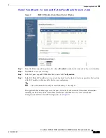
Figure 3

AMM I/O Module Configuration Window

Step 9

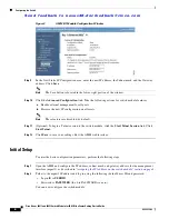
In the New Static IP Configuration area, enter the new IP address, the Subnet mask, and the Gateway 
address. Click 

Save

.

Note

The Save button is located in the lower, right portion of the window.

Step 10

Click the 

Advanced Configuration 

link. Take the following actions for switch module features:

a.

Enable external management for all ports.

b.

Preserve the new IP configuration on all resets.

Note

These features are disabled, by default.

Step 11

(Optional) To begin a Telnet session to the switch module, click the 

Start Telnet Session

 link. Click 

Start Telnet

.

Step 12

Click 

Save

 to save your settings. Exit the AMM web interface.

Initial Setup

To enter the basic configuration parameters, perform the following steps:

Step 1

Open the AMM and configure the IP address, subnet mask, and gateway address for the management 
interface (mgmt1), as described in 

“Assigning the IP Address on the switch module” section on page 4

.

Step 2

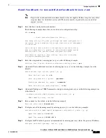
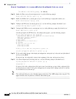
Telnet to the mgmt1 IP address and log in using the following (default) user ID and password:

  •

Login ID is 

USERID

.

  •

Password is 

PASSW0RD

 (the 0 in PASSW0RD is a zero).

You can now configure the switch module.

Summary of Contents for Nexus 4001I

Page 1: ... 10 Overview This guide provides instructions on how to install configure and manage your Cisco Nexus 4001I and 4005I Switch Module for IBM BladeCenter referred to as the switch module in the IBM BladeCenter enclosure and how to set up and configure your switch module For additional installation and configuration information about the switch module see the switch module documentation on Cisco com ...

Page 2: ...s Switch Module 4001I and 4005I for IBM BladeCenter Verifying your Shipping Contents In addition to the switch module the Options Kit contains the following items Warning Before working on equipment that is connected to power lines remove jewelry including rings necklaces and watches Metal objects will heat up when connected to power and ground and can cause serious burns or weld the metal object ...

Page 3: ...s with the switch module Each Cisco module has an internal serial EEPROM that is encoded with security information This encoding provides a way for Cisco to identify and validate that the module meets the requirements for the switch module If the validation fails the software will not bring up the port Connecting to 10 100 1000 Ports The External Management Port on the switch module is a 10 100 10...

Page 4: ...established link If the LED is off the device might not be turned on there might be a cable problem or there might be a problem with the adapter installed in the device Configuring the Switch This section describes how to configure the switch and includes the following topics Assigning the IP Address on the switch module page 4 Initial Setup page 6 Assigning the IP Address on the switch module Whe...

Page 5: ...ve to save your settings Step 7 In the left pane expand I O Module Tasks and click Configuration Step 8 In the I O Module Power Restart area check the check box for the bay that corresponds to the location of the I O module switch module that you are configuring Note The switch module can only be installed in Bays 7 through 10 The applicable bay number appears in the pane followed by other related...

Page 6: ... ports b Preserve the new IP configuration on all resets Note These features are disabled by default Step 11 Optional To begin a Telnet session to the switch module click the Start Telnet Session link Click Start Telnet Step 12 Click Save to save your settings Exit the AMM web interface Initial Setup To enter the basic configuration parameters perform the following steps Step 1 Open the AMM and co...

Page 7: ...e ctrl c at anytime to skip the remaining dialogs Step 4 Enter the setup mode by entering yes or y as in the following example Would you like to enter the basic configuration dialog yes no yes Step 5 Optional Create additional accounts by entering yes or y as in the following example no is the default Create another login account yes no n y Enter the User login Id ID Enter the password for qatest ...

Page 8: ...ord user password role network operator snmp server community topspin ro switchname ibm switch 1 interface mgmt0 ip address 10 10 10 1 255 255 255 0 no shutdown ip route 0 0 0 0 0 10 10 10 100 telnet server enable no ssh server enable Would you like to edit the configuration yes no n Use this configuration and save it yes no y y Step 14 If you want to make changes to the displayed configuration en...

Page 9: ... remote management station For more information about using the CLI see the Cisco Nexus 4001I and 4005I Switch Module for IBM BladeCenter NX OS Command Reference To connect to the switch module console port perform the following steps Step 1 Connect a console cable to the front panel serial port and connect an Ethernet cable to the front panel Ethernet management port Step 2 Start a terminal emula...

Page 10: ...co TelePresence Cisco Unified Computing System Cisco WebEx DCE Flip Channels Flip for Good Flip Mino Flipshare Design Flip Ultra Flip Video Flip Video Design Instant Broadband and Welcome to the Human Network are trademarks Changing the Way We Work Live Play and Learn Cisco Capital Cisco Capital Design Cisco Financed Stylized Cisco Store and Flip Gift Card are service marks and Access Registrar Ai...

Reviews: