• If the modules have burgundy coloring, position the port end of the chassis in the cold aisle.
• If the modules have blue coloring, position the fan trays and power supply end of the chassis in the
cold aisle.
• Make sure that two front-mount brackets are securely fastened to the sides of the chassis at the port end.
• Make sure that you have two customer-supplied rack-mount screws (M6 x 10 mm or appropriate screw
for the vertical mounting rails on the rack).
Step 1
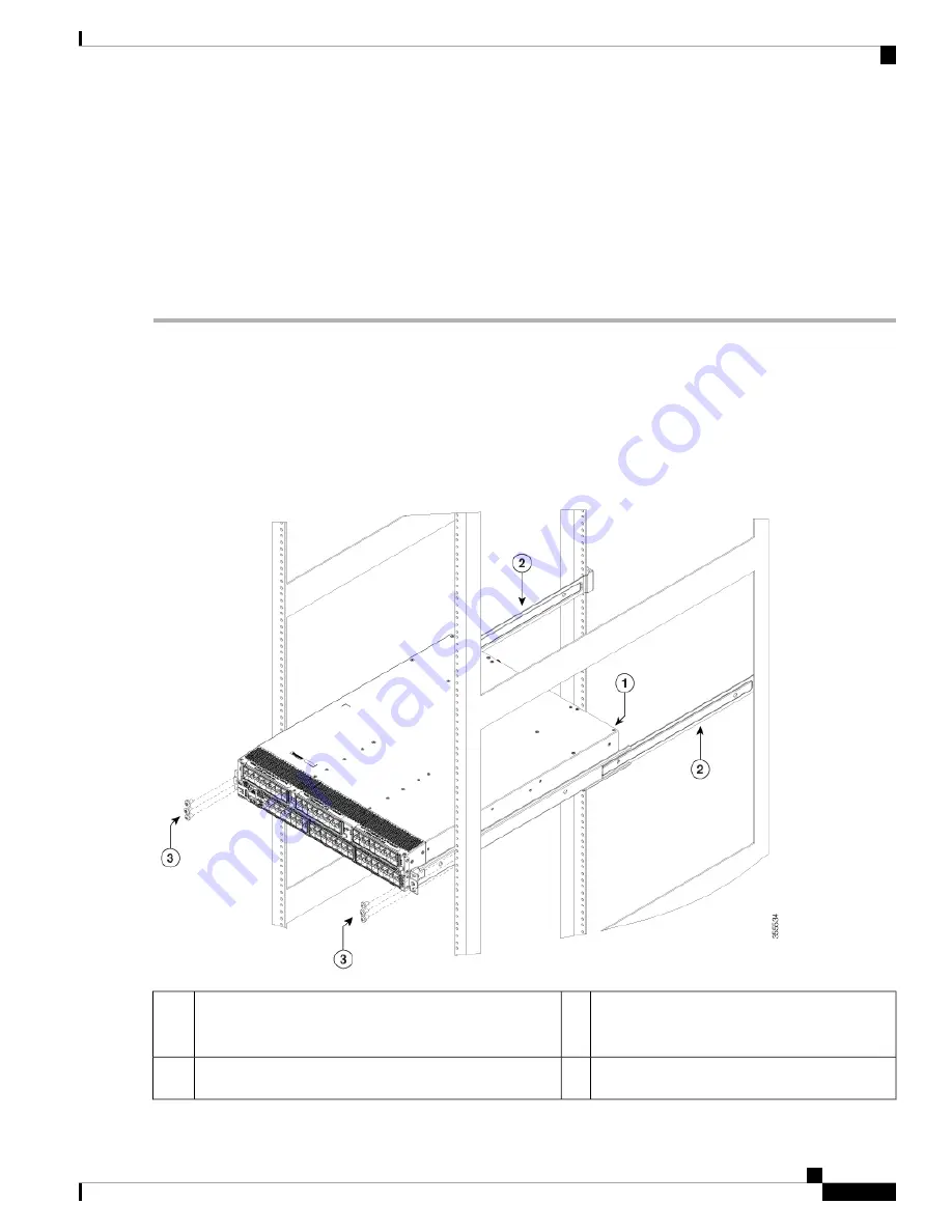
Slide the power supply and fan tray end of the chassis onto the bottom support rails that are installed on the rack. Be sure
that the sides of the chassis by the fan trays and power supplies clips onto the chassis stops on the bottom support rails
and the front mounting brackets come in contact with the rack (see the following figure).
If the bottom support rails are extended a long distance, they can bend outwards slightly when you install the chassis and
the chassis stops at the far end of the rails might not fit into the end of the chassis. If this happens, press the side rails
toward the sides of the chassis so that the chassis stops can go inside the chassis and hold it in place on the rack.
Figure 11: Sliding the Chassis onto the Bottom-Support Rails
Customer-supplied rack-mount screw (M6 x 10
mm screw or other appropriate screw) used to
secure each side of the chassis to the rack.
3
Slide the fan-tray end of the chassis onto the
bottom-support rails so that the chassis locks onto the
chassis stops at the end of the rails.
1
Chassis stops for holding the chassis (installed by the hot
aisle)
2
Cisco MDS 9396T Multilayer Fabric Switch Hardware Installation Guide
33
Installing the Cisco MDS 9396T Switch
Installing the Switch


