background image


6-12

Installing Cisco Intrusion Prevention System Appliances and Modules 5.1

OL-8677-01

Chapter 6      Installing IPS-4260

    Rack Mounting

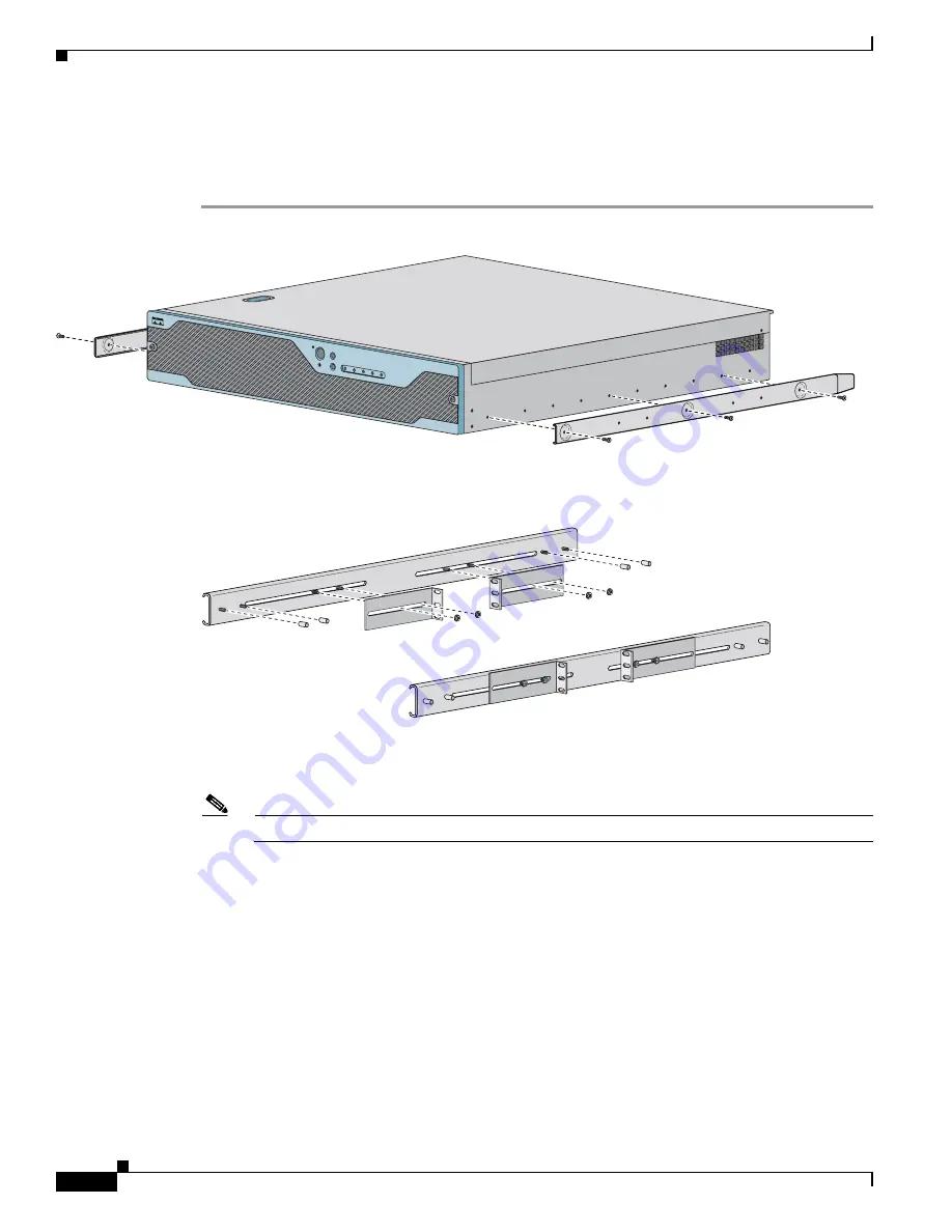
Installing IPS-4260 in a 2-Post Rack

To rack mount IPS-4260 in a 2-post rack, follow these steps:

Step 1

Attach the inner rail to each side of the chassis with three 8-32x1/4” SEMS screws.

Step 2

Using the four inner studs, install the mounting brackets to the outer rail with four 8-32 KEPS nuts. Insert 
four thread covers over the four outer studs on each side.

Step 3

Install the two outer rail subassemblies in the rack using twelve 10-32x1/2” SEMS screws or whatever 
rack hardware is necessary.

Note

Adjust the mounting brackets based on the rack-channel depth.

153320

Cisco IPS 4260 series

Intrusion P

revention S

ensor

POWER

STATUS

FLASH

ID

NIC

RESET

ID

153321

Summary of Contents for IPS-4260

Page 1: ...ds page 6 19 Installing and Removing the Power Supply page 6 21 Caution The BIOS on IPS 4260 is specific to IPS 4260 and must only be upgraded under instructions from Cisco with BIOS files obtained from the Cisco website Installing a non Cisco or third party BIOS on IPS 4260 voids the warranty For more information on how to obtain instructions and BIOS files from the Cisco website see Obtaining Ci...

Page 2: ...ns the hardware bypass feature Initially IPS 4260 supports only the built in interfaces and these two interface cards For more information on the 4GE bypass interface card see Hardware Bypass page 6 3 IPS 4260 monitors greater than 1 Gbps of aggregate network traffic on multiple sensing interfaces and is also inline ready It replaces IDS 4250 XL It supports both copper and fiber interfaces Note Th...

Page 3: ...total fiber monitoring interfaces The 2SX interface cards does not support hardware bypass Figure 6 2 shows the 2SX card Figure 6 2 2SX Interface Card Hardware Bypass This section describes the 4GE bypass interface card and its configuration restrictions For the procedure for installing and removing the 4GE bypass interface card see Installing and Removing PCI Cards page 6 19 This section contains...

Page 4: ...dby mode If the sensor is powered off reset or if the NIC interfaces fail or are unloaded those paired interfaces enter fail open state in hardware traffic flows unimpeded through inline interface Any other inline interfaces enter fail closed state When bypass is set to AUTO traffic flows without inspection software bypass is activated if sensorApp fails For each inline interface on which hardware...

Page 5: ...tonegotiation must be set on MDI X switch ports connected to IPS 4260 You must configure both the sensor ports and the switch ports for autonegotiation for hardware bypass to work The switch ports must support MDI X which automatically reverses the transmit and receive lines if necessary to correct any cabling problems The sensor is only guaranteed to operate correctly with the switch if both of t...

Page 6: ...indicator is off when power is turned off or the power source is disrupted Flash green amber Off when the compact flash device is not being accessed Blinks green when the compact flash device is being accessed Solid amber when a device has failed Status green amber Blinks green while the power up diagnostics are running or the system is booting Solid green when the system has passed power up diagn...

Page 7: ...e System ID indicator Status indicator Table 6 2 Back Panel Indicators Indicator Color Description Left side Green solid Green blinking Physical link Network activity Right side Not lit Green Amber 10 Mbps 100 Mbps 1000 Mbps Table 6 3 Power Supply Indicators Color Description Off No AC power to all power supplies Green solid Output on and ok Green blinking AC present only 5Vsb on power supply off ...

Page 8: ...evice Statement 1071 SAVE THESE INSTRUCTIONS Table 6 4 IPS 4260 Specifications Dimensions and Weight Height 3 45 in 87 6 cm Width 17 14 in 435 3 cm Depth 20 in 508 cm Weight 40 0 lb 18 14 kg Form factor 2 RU standard 19 inch rack mountable Power Autoswitching 100V to 240V AC Frequency 47 to 63 Hz single phase Operating current 8 9 A Steady state 588 W max continuous Maximum peak 657 W Maximum heat...

Page 9: ...al bracket RJ45 console cable Two 6 ft Ethernet cables Rack Mounting You can rack mount IPS 4260 in a 2 or 4 post rack This section describes how to rack mount IPS 4260 and contains the following topics Installing IPS 4260 in a 4 Post Rack page 6 9 Installing IPS 4260 in a 2 Post Rack page 6 12 Installing IPS 4260 in a 4 Post Rack To rack mount IPS 4260 in a 4 post rack follow these steps Step 1 A...

Page 10: ...to the chassis with two 8 32x1 4 SEMS screws You can flip the bracket to push the system forward in the rack Step 3 Using the four inner studs install the mounting brackets to the outer rail with four 8 32 KEPS nuts Insert four thread covers over the four outer studs on each side 153315 Cisco IPS 4260 series Intrusion Prevention Sensor POWER STATUS FLASH ID NIC RESET ID 153316 ...

Page 11: ...nuts if necessary Note Adjust the mounting brackets based on rack depth Step 5 Slide IPS 4260 into the rack making sure the inner rail is aligned with the outer rail Step 6 Install two 10 32x1 2 SEMS screws to hold the front tab mounting bracket to the rail 153317 153318 Cisco IPS 4260 series Intrusion Prevention Sensor POWER STATUS FLASH ID NIC RESET ID Cisco IPS 4260 series Intrusion Prevention ...

Page 12: ...ee 8 32x1 4 SEMS screws Step 2 Using the four inner studs install the mounting brackets to the outer rail with four 8 32 KEPS nuts Insert four thread covers over the four outer studs on each side Step 3 Install the two outer rail subassemblies in the rack using twelve 10 32x1 2 SEMS screws or whatever rack hardware is necessary Note Adjust the mounting brackets based on the rack channel depth 1533...

Page 13: ...nting Step 4 Slide IPS 4260 into the rack making sure the inner rail is aligned with the outer rail Step 5 Install four 8 32x7 16 SEMS screws through the clearance slots in the side of each outer rail assembly into the inner rail 153322 153323 Cisco IPS 4260 series Intrusion Prevention Sensor POWER STATUS FLASH ID NIC RESET ID ...

Page 14: ...orming these steps by reading the safety warnings in Regulatory Compliance and Safety Information for the Cisco Intrusion Prevention System 4200 Series Appliance Sensor For more information on working with electrical power and in an ESD environment see Site and Safety Guidelines page 1 23 To install IPS 4260 on the network follow these steps Step 1 Position IPS 4260 on the network Step 2 Attach th...

Page 15: ...UPS is recommended Step 5 Connect the cable as shown in Step 6 so that you have either a DB 9 or DB 25 connector on one end as required by the serial port for your computer and the other end is the RJ 45 connector Note Use the console port to connect to a computer to enter configuration commands Locate the serial cable from the accessory kit The serial cable assembly consists of a 180 rollover cab...

Page 16: ...and control port GigabitEthernet2 0 through GigabitEthernet2 3 and GigabitEthernet3 0 through 3 3 are the additional expansion port slots Caution Management and console ports are privileged administrative ports Connecting them to an untrusted network can create security concerns Step 8 Power on IPS 4260 153309 RJ 45 to DB 9 or DB 25 serial cable null modem Computer serial port DB 9 or DB 25 MGMT C...

Page 17: ...device is rated not greater than 120 VAC 20 A U S 240 VAC 16 20 A International Statement 1005 Warning This equipment must be grounded Never defeat the ground conductor or operate the equipment in the absence of a suitably installed ground conductor Contact the appropriate electrical inspection authority or an electrician if you are uncertain that suitable grounding is available Statement 1024 War...

Page 18: ... Step 3 Power off IPS 4260 Step 4 Remove the power cord and other cables from IPS 4260 Step 5 If rack mounted remove IPS 4260 from the rack For the procedure see Rack Mounting page 6 9 Step 6 Place IPS 4260 in an ESD controlled environment For more information see Working in an ESD Environment page 1 25 Step 7 Press the blue button on the top of the chassis cover and slide the chassis cover back C...

Page 19: ...ards page 6 2 Note We recommend that you install the 4GE bypass interface card in slot 2 if you are installing only one 4GE bypass card This improves accessibility to the RJ45 cable connectors To install and remove PCI cards follow these steps Step 1 Log in to the CLI Step 2 Prepare IPS 4260 to be powered off sensor reset powerdown Wait for the power down message before continuing with Step 3 Note...

Page 20: ...pressing on it from inside the chassis If the card is full length use a screw driver to remove the blue thumb screw from the card support at the back of the card carrier Step 11 Carefully align the PCI card with the PCI Express connector and alignment grooves for the appropriate slot Apply firm even pressure until the card is fully seated in the connector Step 12 Reinstall the slot cover screw to ...

Page 21: ...upplies follow these steps Step 1 Log in to the CLI Step 2 Prepare IPS 4260 to be powered off sensor reset powerdown Wait for the power down message before continuing with Step 3 Note You can also power down IPS 4260 using IDM For the procedure refer to Resetting the Appliance Step 3 Power off IPS 4260 Step 4 Remove the power cord and other cables from IPS 4260 Note Power supplies are hot swappabl...

Page 22: ... Installing IPS 4260 Installing and Removing the Power Supply Step 6 Install the power supply Step 7 To remove the power supply push down the green tab and pull out the power supply Step 8 After installing or removing the power supply replace the power cord and other cables Step 9 Power on IPS 4260 ...

Reviews: