Statement 1032—
Lifting the Chassis
To prevent personal injury or damage to the chassis, never attempt to lift or tilt the chassis using the
handles on modules, such as power supplies, fans, or cards. These types of handles are not designed to
support the weight of the unit.
Warning
Step 1
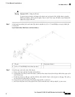
Attach a rack mount bracket to each side of the chassis using the six 8-32 x .375-inch Phillips screws provided in the
accessory kit.
Figure 35: Attach the Rack Mount Bracket to the Side of the Chassis
Rack-mount bracket
2
Chassis
1
8-32 x .375-inch Phillips screws (three per side)
3
Step 2
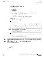
Attach the inner rails to the sides of the chassis:
a) Remove the inner rails from the slide rail assemblies.
b) Align an inner rail with one side of the chassis so that the three keyed slots in the rail align with the three pegs on the
side of the chassis.
c) Set the keyed slots over the pegs, and then slide the rail toward the front to lock it in place on the pegs. The rear key
slot has a metal clip that locks over the peg.
d) Secure the inner rail to the side of the chassis using one M3 x 6 mm screw.
e) Install the second inner rail to the opposite side of the chassis and secure with the other M3 x 6 mm screw.
Cisco Firepower 4110, 4120, 4140, and 4150 Hardware Installation Guide
49
Rack-Mount and Ground the Chassis
Rack-Mount the Chassis

