3-11
Cisco 1120 Connected Grid Router Hardware Installation Guide
OL-26438-02
Chapter 3 Router Hardware Description
Hardware Features
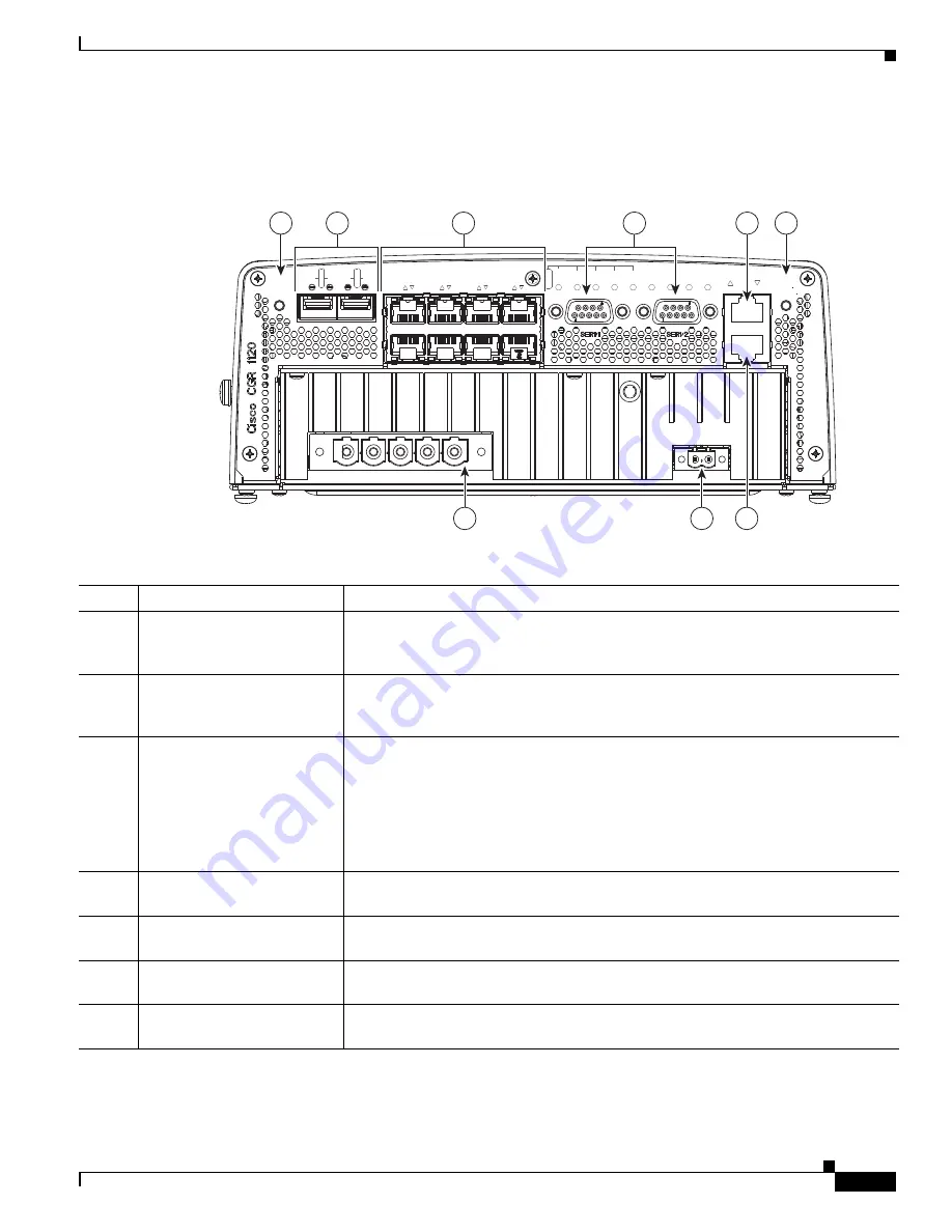
Cable Panel (Back Panel) Features
Figure 3-5
Cable Panel (Back Panel) Features
Table 3-5
Cable Panel (Back Panel) Features
Item
Feature
Description
1
CONFIG Reset button
Press for at least 5 seconds to return the router software configuration to the factory
default, and power cycle the router. For information on how to use this feature,
including a Caution statement, see
CONFIG Reset Button, page 3-12
.
2
SFP ports
Install supported small-form-factor pluggable (SFP) modules in these two SFP ports,
labeled ETH 2/1 and ETH 2/2. For more information and supported SFPs, see
Small
Form-Factor Pluggable (SFP) Ports, page 3-12
.
3
Ethernet ports:
•
2–Gigabit Ethernet
(10/100/1000 Mbps)
•
6–Fast Ethernet
(10/100 Mbps)
Make network connections using the Ethernet ports. For more information, see
Ethernet Ports, page 3-13
.
•
Gigabit Ethernet (GE) ports—GE ports ETH 2/1 and ETH 2/2 are WAN ports
for connectivity to a primary substation or a control center.
•
Fast Ethernet (FE) ports —FE ports ETH 2/3 to ETH2/8 are LAN ports for local
network devices.
4
Serial ports
Connect the router to legacy devices using these two serial ports. For more
information on these ports and supported devices, see
Serial Ports, page 3-15
.
5
Console port
Connect a console or PC to the asynchronous console port to manage the router with
a local connection.
6
PWR RESET button
Press the PWR RESET button for at least 5 seconds to power cycle the router. For
more information on how to use this feature, see
PWR RESET Button, page 3-12
.
7
AC power supply connector
Connect the router to the AC power supply (included). For more information, see
AC
Power Supply, page 3-17
.
302210
RESET
SPD
EN
SFP 0/1
SPD
EN
SFP 0/0
GE 0/1
GE 0/0
FE 0/5
FE 0/4
FE 0/3
FE 0/2
FE 0/1
FE 0/0
ALARM
OUT 1
IN 4
IN 3
IN 2
IN 1
GPS
WIFI
AC
T
SYS
ALARM
CONSOLE
PO
WER
PE
N
L3
L2
L1
+
-
1
5
6
7
8
9
2
3
4


