background image

15

Catalyst 6500 Series DFC, DFC3A, DFC3B, and DFC3BXL Installation Note

78-11627-04

Installing the DFC

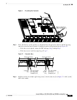
Figure 9

Preseating the Connector

Step 8

Verify that the keys on the connector are aligned and that the gap between the key and the opposing 
connector is no more than 1/16 inch (1.6 mm) before fully seating the module (see 

Figure 10

):

If the keys are not aligned, remove the DFC and repeat 

Step 4

 through 

Step 7

.

If the keys are not seated far enough, repeat 

Step 7

.

Figure 10

Connector Keys

Step 9

With the bottom of your hand, apply firm pressure to the location shown in 

Figure 11

 to fully seat the 

DFC on the module. 

WS-X5530

52721

STA

TUS

LINE

LINE

1

1

2

LINE

LINE

3

4

LINE

LINE

5

6

LINE

LINE

7

8

LINE

LINE

9

10

LINE

LINE

11

12

LINE

LINE

13

14

LINE

LINE

15

16

2

3

4

5

6

7

8

9

10

11

12

13

14

15

16

Apply pressure

here

Move up and down
with your other hand

Board connector

Standoff threads 
not completely 
through board

Standoff threads 
completely 
through board

Board connector

Unseated

key

Fully

seated

key

52722

Summary of Contents for DFC3A

Page 1: ...noted the term DFC refers to the DFC DFC3A DFC3B and DFC3BXL This publication describes how to install the Catalyst 6500 series Distributed Forwarding Card DFC on Catalyst 6500 series fabric enabled modules Note You can only install the DFC on fabric enabled modules See the Hardware and Software Requirements section on page 2 for more information Contents This publication contains these sections H...

Page 2: ...ou need the following Catalyst 6500 series switch Catalyst 6506 6509 6509 NEB or 6513 or Cisco 7600 series router Cisco 7606 7609 or 7613 Supervisor Engine 2 with Multilayer Switch Feature Card 2 MSFC2 running Cisco IOS software on the Supervisor Engine 2 and MSFC2 Note You cannot have a DFC in a system with a Supervisor Engine 720 Fabric enabled module Switch Fabric Module SFM WS C6500 SFM or SFM...

Page 3: ...th a Supervisor Engine 2 Fabric enabled module Note Supervisor Engine 720 supports a DFC3A DFC3B or DFC3BXL on these WS X6516 GBIC hardware revisions Lower than 5 0 5 4 and higher Supervisor Engine 720 does not support a DFC3A DFC3B or DFC3BXL on WS X6516 GBIC hardware revisions 5 0 through 5 3 With a Supervisor Engine 720 and with a DFC3A DFC3B or DFC3BXL installed WS X6516 GBIC hardware revision...

Page 4: ...sche schakelingen betrokken risico s en dient u op de hoogte te zijn van de standaard praktijken om ongelukken te voorkomen Voor een vertaling van de waarschuwingen die in deze publicatie verschijnen dient u de vertaalde veiligheidswaarschuwingen te raadplegen die bij dit apparaat worden geleverd Opmerking BEWAAR DEZE INSTRUCTIES Opmerking Deze documentatie dient gebruikt te worden in combinatie m...

Page 5: ...Gebrauch in Verbindung mit dem Installationshandbuch für Ihr Gerät bestimmt das dem Gerät beiliegt Entnehmen Sie bitte alle weiteren Informationen dem Handbuch Installations oder Konfigurationshandbuch o Ä für Ihr spezifisches Gerät Figyelem FONTOS BIZTONSÁGI ELÕÍRÁSOK Ez a figyelmezetõ jel veszélyre utal Sérülésveszélyt rejtõ helyzetben van Mielõtt bármely berendezésen munkát végezte legyen figye...

Page 6: ...tação destina se a ser utilizada em conjunto com o manual de instalação incluído com o produto específico Consulte o manual de instalação o manual de configuração ou outra documentação adicional inclusa para obter mais informações Advertencia INSTRUCCIONES IMPORTANTES DE SEGURIDAD Este símbolo de aviso indica peligro Existe riesgo para su integridad física Antes de manipular cualquier equipo consi...

Page 7: ...04 Parts List Warning Only trained and qualified personnel should be allowed to install replace or service this equipment Parts List These parts are in the DFC kit One Catalyst 6500 series DFC DFC3A DFC3B or DFC3BXL One disposable grounding wrist strap One bag of mounting screws ...

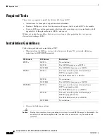
Page 8: ...FC in a system with a Supervisor Engine 720 observe the following restrictions for DFC3 PFC3 mismatch Observe the following cautions Caution During this procedure wear grounding wrist straps to avoid ESD damage to the module Do not directly touch the backplane with your hand or any metal tool or you could shock yourself PFC Version DFC Version Restrictions PFC3A DFC3A No restrictions DFC3B The DFC...

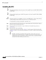
Page 9: ... refers to the DFC DFC3A DFC3B and DFC3BXL Note The figures in this procedure show the DFC The procedure is the same for the DFC DFC3A DFC3B and DFC3BXL Caution During this procedure wear grounding wrist straps to avoid ESD damage to the module Do not directly touch the backplane with your hand or any metal tool or you could shock yourself To remove the DFC perform these steps Step 1 Remove the mo...

Page 10: ...nectors Figure 2 Disconnecting the DFC from the Module WS X5530 120912 STATUS LINE LINE 1 1 2 LINE LINE 3 4 LINE LINE 5 6 LINE LINE 7 8 LINE LINE 9 10 LINE LINE 11 12 LINE LINE 13 14 LINE LINE 15 16 2 3 4 5 6 7 8 9 10 11 12 13 14 15 16 Cap nuts 2 Screws 12 WS X5530 120865 STATUS LINE LINE 1 1 2 LINE LINE 3 4 LINE LINE 5 6 LINE LINE 7 8 LINE LINE 9 10 LINE LINE 11 12 LINE LINE 13 14 LINE LINE 15 16...

Page 11: ...re 4 Figure 4 Removing the DFC Step 7 Place the removed DFC on an antistatic mat or antistatic foam pad WS X5530 120866 STATUS LINE LINE 1 1 2 LINE LINE 3 4 LINE LINE 5 6 LINE LINE 7 8 LINE LINE 9 10 LINE LINE 11 12 LINE LINE 13 14 LINE LINE 15 16 2 3 4 5 6 7 8 9 10 11 12 13 14 15 16 Lift board here to disconnect power connector WS X5530 120867 STATUS LINE LINE 1 1 2 LINE LINE 3 4 LINE LINE 5 6 LI...

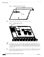
Page 12: ...from the Catalyst 6500 series switch Refer to the Catalyst 6500 Series Module Installation Guide for removal instructions Step 2 Place the module on an antistatic mat or foam with the front of the module facing toward you see Figure 6 Step 3 Remove the DFC from its antistatic bag Step 4 Align the two mounting holes on the DFC see Figure 5 with the two male standoffs on the module see Figure 6 Make...

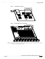
Page 13: ... 5 Ensure that the connectors on the DFC are aligned with the connectors on the module Figure 7 shows the connectors on the underside of the DFC 47084 Align with the male standoffs on the module WS X5530 47083 STATUS LINE LINE 1 1 2 LINE LINE 3 4 LINE LINE 5 6 LINE LINE 7 8 LINE LINE 9 10 LINE LINE 11 12 LINE LINE 13 14 LINE LINE 15 16 2 3 4 5 6 7 8 9 10 11 12 13 14 15 16 Male standoffs ...

Page 14: ...ligned will damage the connectors on both the DFC and the module If you damage a connector you will have to return the module to Cisco for repair It is important that the DFC is preseated prior to being fully seated Step 7 With your left hand apply firm pressure at the location shown in Figure 9 While applying pressure with your left hand move the DFC up and down with your right hand no more than ...

Page 15: ...tep 7 If the keys are not seated far enough repeat Step 7 Figure 10 Connector Keys Step 9 With the bottom of your hand apply firm pressure to the location shown in Figure 11 to fully seat the DFC on the module WS X5530 52721 STATUS LINE LINE 1 1 2 LINE LINE 3 4 LINE LINE 5 6 LINE LINE 7 8 LINE LINE 9 10 LINE LINE 11 12 LINE LINE 13 14 LINE LINE 15 16 2 3 4 5 6 7 8 9 10 11 12 13 14 15 16 Apply pres...

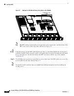
Page 16: ...ted by visually verifying that there is no gap between the male and female keys on the connectors and that the bottom of the DFC is in contact with the tops of the standoffs see Figure 10 Step 10 Use a Phillips head screwdriver to install the two screws at the front of the DFC and the one screw at the power connector in the order shown in Figure 12 Note You should visually verify that there are st...

Page 17: ... Figure 13 Installing the Second Set of Screws and Cap Nuts WS X5530 52723 STATUS LINE LINE 1 1 2 LINE LINE 3 4 LINE LINE 5 6 LINE LINE 7 8 LINE LINE 9 10 LINE LINE 11 12 LINE LINE 13 14 LINE LINE 15 16 2 3 4 5 6 7 8 9 10 11 12 13 14 15 16 Install these first 1 2 3 WS X5530 48443 STATUS LINE LINE 1 1 2 LINE LINE 3 4 LINE LINE 5 6 LINE LINE 7 8 LINE LINE 9 10 LINE LINE 11 12 LINE LINE 13 14 LINE LI...

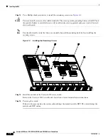
Page 18: ...hould visually verify that there are standoffs beneath the mounting holes before installing the securing screws Figure 14 Installing the Remaining Screws Step 13 Install the module in the Catalyst 6500 series switch Refer to the Catalyst 6500 Series Module Installation Guide for installation instructions Step 14 Power up the switch If the switch comes online the system acknowledges the module and ...

Page 19: ...ftware Configuration Guide Catalyst 6500 Series Switch Cisco IOS Command Reference Catalyst 6500 Series DFC Memory Upgrade Installation Note Obtaining Documentation Obtaining Documentation and Submitting a Service Request For information on obtaining documentation submitting a service request and gathering additional information see the monthly What s New in Cisco Product Documentation which also ...

Page 20: ... Cisco Press Cisco Systems Cisco Systems Capital the Cisco Systems logo Cisco Unity Enterprise Solver EtherChannel EtherFast EtherSwitch Fast Step Follow Me Browsing FormShare GigaDrive HomeLink Internet Quotient IOS iPhone IP TV iQ Expertise the iQ logo iQ Net Readiness Scorecard iQuick Study LightStream Linksys MeetingPlace MGX Networkers Networking Academy Network Registrar PIX ProConnect Scrip...

Reviews: