


2-4
Cisco Catalyst Blade Switch 3040 for FSC Hardware Installation Guide
OL-10694-01
Chapter 2 Blade Switch Installation
BX600 System Architecture
These items ship with your blade switch:
•
Console cable
•
Cisco Catalyst Blade Switch 3040 for FSC Getting Started Guide
•
Regulatory Compliance and Safety Information for the Cisco Catalyst Blade Switch 3040 for FSC
•
Registration card
Note
If the blade switches are ordered with the BX600 system, the blade switches are already installed, and
no unpacking is required. The unpacking procedure applies only if a blade switch is ordered separately.
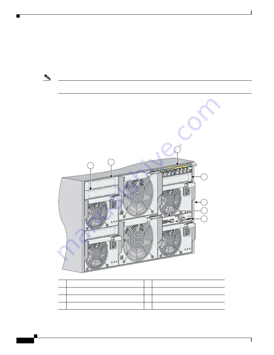
BX600 System Architecture
The four chassis I/O module slots are on the rear panel (see
Figure 2-1
). You can insert blade switches
into the NET1, NET2, NET3, and NET4 I/O blade bays.
Figure 2-1
Rear View of the BX600 System
1
NET1 slot (with blade switch installed)
5
Rear panel of the BX600 system
2
NET2 slot
6
BX600 system management blade
3
NET3 slot
7
Advanced KVM
1
blade
1.
KVM = Keyboard, video, and mouse connection
4
NET4 slot
190181
11x
12x
13x
14x
15x
16x
Console
11x
12x
13x
14x
15x
16x
2
1
3
5
6
4
7


