


4-3
Cisco 7201 Installation and Configuration Guide
OL-11364-04
Chapter 4 Replacing Cisco 7201 Field-Replaceable Units
Removing and Installing the CompactFlash Disk
Step 1
Attach an ESD-preventive wrist strap between you and an unpainted chassis surface.
Step 2
Locate the label on the SFP module and turn the SFP module so the label is on top and the alignment
groove is on the bottom.
Note
The SFP module is keyed so that it cannot be inserted incorrectly.
Step 3
Insert the SFP module into Gigabit Ethernet port 0/0, 0/1, 0/2, or 0/3. The SFP module snaps into place
when you have completely and properly inserted it.
Step 4
Repeat Step 2 and Step 3 if you are inserting a second, third, or fourth SFP module.
Note
Do not remove the plug from the SFP optical bores until you are ready to install the network interface
optical fiber cable. Save the plug for future use.
Step 5
Clean the optical fiber cable before attaching it to the SFP module. For information, see the
Inspection
and Cleaning Procedures for Fiber-Optic Connections
document and the
Compressed Air Cleaning Issues for
Fiber-Optic Connections
document.
This completes the SFP module installation procedure.
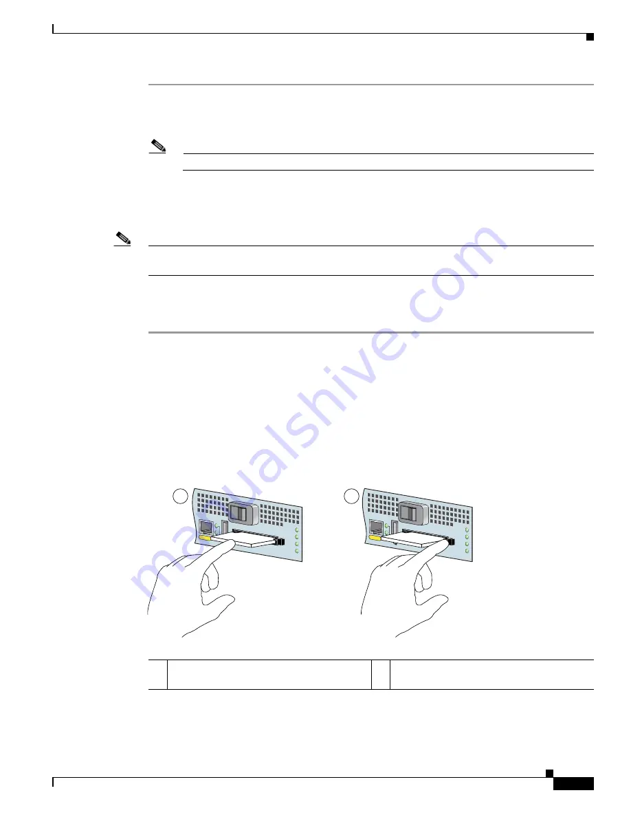
Removing and Installing the CompactFlash Disk
For CompactFlash Disk specifications and product numbers, see
Appendix A, “Specifications.”
For use
of the CompactFlash Disk, also see
Appendix B, “Using the CompactFlash Disk.”
Figure 4-2
Installing and Removing a CompactFlash Disk
1
Inserting the CompactFlash Disk
2
Pressing the ejector button to release the
CompactFlash Disk
MNGMNT USE ONL
Y
FE
LINK
0
FE 0/0
ALARM
PWR OK
STATUS
CF
ACTV
COMPACT FLASH
170871
2
1
MNGMNT USE ONL
Y
FE
LINK
0
FE 0/0
ALARM
PWR OK
STATUS
CF
ACTV
COMPACT FLASH


