background image


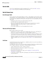
3-6

Catalyst 3560-C and 2960-C Switch Hardware Installation Guide

OL-23803-02

Chapter 3      Troubleshooting

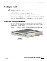
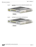
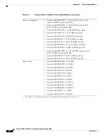
Finding the Switch Serial Number

Figure 3-2

Serial Number Location for the Catalyst 3560CG-8PC-S, 3560CG-8PC-S, and the 
3560CG-8TC-S 

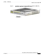
Figure 3-3

Serial Number Location for the Catalyst 3560CPD-8PT-S Switch

MODE

SPD

PoE

DPLX

STAT 
SYST

1

2

3

4

5

6

7

8

2

1

CONS

OLE

PO

WER

 OV

ER 

ETH

ERN

ET

9

9

Serie

s PoE

S

N: XXXNNNNXXXX

20

8

9

8

2

MODE

SPD

PoE

DPLX

STAT 
SYST

Cata

lyst 3560-C

G S

erie

sPD

1

2

3

4

5

6

7

8

2

1

CONS

OLE

PO

WER

 OV

ER 

ETH

ERN

ET

S

N: XXXNNNNXXXX

20921

8

Summary of Contents for 2960-C

Page 1: ...stems Inc 170 West Tasman Drive San Jose CA 95134 1706 USA http www cisco com Tel 408 526 4000 800 553 NETS 6387 Fax 408 527 0883 Catalyst 3560 C and 2960 C Switch Hardware Installation Guide March 2013 Text Part Number OL 23803 02 ...

Page 2: ...cur in a particular installation If the equipment causes interference to radio or television reception which can be determined by turning the equipment off and on users are encouraged to try to correct the interference by using one or more of the following measures Reorient or relocate the receiving antenna Increase the separation between the equipment and receiver Connect the equipment into an ou...

Page 3: ...ts Catalyst 2960CPD 8TT L 2960CPD 8PT L and 3560CPD 8PT S 1 8 PoE Capable Downlink Ports Catalyst 2960CPD 8PT L 3560CG 8PC S 3560CPD 8PT S 2960C 8PC L 2960C 12PC L 3560C 8PC S and 3560C 12PC S 1 9 USB Type A Port 1 9 Dual Purpose Ports 1 9 SFP Modules 1 9 Management Ports 1 11 LEDs 1 12 Switch Panel LEDs 1 12 System LED 1 13 Console LEDs 1 13 Modes for Port LEDs 1 14 Port LEDs 1 14 PoE LED 1 15 PD...

Page 4: ...crews 2 13 Mounting Tray with a Magnet 2 15 In a Rack 2 18 Attaching Brackets to the Switch 2 18 Mounting the Switch in a Rack 2 19 On a DIN Rail 2 20 Attaching the DIN Mount Tray to the Switch 2 20 Mounting the Switch on a DIN Rail 2 21 Removing the Switch from a DIN Rail 2 23 Installing a Cover for the Reset Button Optional 2 24 Installing the Power Cord Retainer Optional 2 25 Installing the Cab...

Page 5: ...Technical Specifications A 1 A P P E N D I X B Connector and Cable Specifications B 1 Connector Specifications B 1 10 100 and 10 100 1000 Ports B 1 SFP Module Connectors B 2 Dual Purpose Ports B 2 Cables and Adapters B 3 SFP Module Cables B 3 Cable Pinouts B 4 Console Port Adapter Pinouts B 5 A P P E N D I X C Configuring the Switch with the CLI Setup Program C 1 Accessing the CLI Through the Cons...

Page 6: ...ion Guide OL 23803 02 Uninstalling the Cisco Microsoft Windows XP and 2000 USB Driver C 6 Uninstalling the Cisco Microsoft Windows Vista and Windows 7 USB Driver C 6 Entering the Initial Configuration Information C 7 IP Settings C 7 Completing the Setup Program C 7 ...

Page 7: ...ion Means reader be careful In this situation you might do something that could result in equipment damage or loss of data The safety warnings for this product are translated into several languages in the Regulatory Compliance and Safety Information for the Catalyst 3560 C and 2960 C Switches that is available on Cisco com The EMC regulatory statements are also included in that guide Warning IMPOR...

Page 8: ...For other information about related products see these documents Smart Install Configuration Guide Auto Smartports Configuration Guide Cisco EnergyWise Configuration Guide Cisco SFP module documents http www cisco com en US products hw modules ps5455 prod_installation_guides_list html SFP module compatibility matrix documents http www cisco com en US products hw modules ps5455 products_device_supp...

Page 9: ...2 Rear Panel page 1 16 Management Options page 1 18 Switch Models Table 1 1 Switch Model Descriptions Switch Model Description Catalyst 2960CPD 8TT L 8 10 100 Ethernet ports and 2 10 100 1000BASE T PD uplink copper ports Catalyst 2960CPD 8PT L 8 10 100 PoE1 ports and 2 10 100 1000BASE T PD uplink copper ports Catalyst 2960CG 8TC L 8 10 100 1000 Ethernet ports and 2 dual purpose ports 1 10 100 1000...

Page 10: ...mini Type B console port USB Type A port available on the Catalyst 3560CPD 8PT S 2960CG 8TC L 3560CG 8PC S and 3560CG 8TC S switches LEDs All the 8 port and 12 port switches have similar components See Figure 1 1 Figure 1 2 Figure 1 3 Figure 1 4 and Figure 1 5 for examples Catalyst 3560C 8PC S 8 10 100 PoE ports and 2 dual purpose ports Catalyst 3560C 12PC S 12 10 100 PoE ports and 2 dual purpose ...

Page 11: ...onsole port 5 10 100 PoE ports 3 RJ 45 console port 6 10 100 1000 uplink ports M O DE CONSOLE 1 2 Seri es PD PO W ER O VER ETHERNET 1 2 3 4 5 6 7 8 PD SPD PoE DPLX STAT SYST 282391 2 5 1 6 3 4 1 Mode button 5 LEDs 2 USB Type A port 6 10 100 1000 PoE ports 3 USB mini Type B console port 7 Dual purpose ports 4 RJ 45 console port M O DE CONSOLE 9 Catal yst3560 CG Seri es PoE PO W ER O VER ETHERNET 1 ...

Page 12: ...0 PoE ports 3 USB mini Type B console port 7 10 100 1000 uplink ports 4 RJ 45 console port M O DE CONSOLE Catal yst3560 CG Seri es PD PO W ER O VER ETHERNET 1 2 3 4 SPD PoE PD DPLX STAT SYST 5 6 7 8 1 2 208867 3 6 1 2 7 4 5 1 Mode button 4 LEDs 2 USB mini Type B console port 5 10 100 PoE ports 3 RJ 45 console port 6 Dual purpose ports M ODE CONSOLE 1 2 Cat al yst2960 C Ser i esPoE POW EROVERETHERN...

Page 13: ...rs with Ethernet pinouts The maximum cable length is 328 feet 100 meters The 100BASE TX and 1000BASE T traffic requires Category 5 Category 5e or Category 6 unshielded twisted pair UTP cable The 10BASE T traffic can use Category 3 or Category 4 UTP cable For information about port connections and port specifications see the Connecting to the 10 100 and 10 100 1000 Ports section on page 2 33 PoE Po...

Page 14: ...power negotiation power reservation and per port power policing For information about configuring and monitoring PoE ports see the switch software configuration guide on Cisco com For information about port connections and port specifications see the Connecting to the 10 100 and 10 100 1000 Ports section on page 2 33 Note The output of the PoE circuit has been evaluated as a Limited Power Source L...

Page 15: ... receiving power from the PoE downlink port 3 Catalyst 2960 C switch 282392 Catalyst 3750 X PoE 48 SYST XPS STAT SPEED DUPLX EN PoE STACK MAST S PWR MODE CONSOL E 1 2 3 4 5 6 7 8 9 10 11 12 13 14 15 16 17 18 19 20 21 22 23 24 25 26 27 28 29 30 31 32 33 34 35 36 37 38 39 40 41 42 43 44 45 46 47 48 C3KX NM 10G NETWORK MODULE G1 G2 TE1 G3 G4 TE2 MODE CONSOLE 1 2 Series PD POWER OVER ETHER NET 1 2 3 4...

Page 16: ...nformation Table 1 2 PoE Budgeting for the Catalyst 2960CPD 8PT L Powering Options on the Uplink Ports Power Sent from Uplink Switches Available PoE budget 1 PoE uplink 15 4 W 2 PoE uplinks 30 8 W 7 W 1 PoE uplink 30 W 7 W 2 PoE uplinks 60 W 22 4 W 1 PoE and 1 PoE uplink 45 4 W 15 4 W I Cisco UPOE uplink 60 W 30 8 W1 2 Cisco UPOE uplinks 120 W 30 8 W1 1 The second UPOE uplink is a backup Auxiliary...

Page 17: ...ference on Cisco com Dual Purpose Ports You can configure the dual purpose ports on the switch as either 10 100 1000 ports or as SFP module ports You can set the 10 100 1000 ports to autonegotiate or you can configure them as fixed 10 100 or 1000 Mb s Gigabit Ethernet ports By default the switch selects the medium for each dual purpose port 10 100 1000BASE T or SFP When a link is achieved on one m...

Page 18: ... Windows USB device driver on the device that is connected to the USB mini console port and that is running Microsoft Windows Note For information about downloading the Cisco USB device driver see the Installing the Cisco Microsoft Windows USB Device Drivers section on page C 4 With the Cisco Windows USB device driver connecting and disconnecting the USB cable from the console port does not affect...

Page 19: ...rformance Switch Panel LEDs Figure 1 8 Switch LEDs 1 Mode button 5 SPD LED speed 2 SYST LED system 6 PoE LED1 1 Applicable to switches with PoE ports 3 STAT LED status 7 PD LED2 powered device 2 Only the Catalyst 2960CPD 8PT L and 3560PD 8PT S switches have the PD LED 4 DPLX LED duplex 8 Port LEDs M O DE CONSOLE PO W ER O VER ETHERNET 1 2 3 4 5 6 7 8 PD SPD PoE DPLX STAT SYST 282393 6 7 5 8 2 3 4 ...

Page 20: ... cables the USB mini console port has priority Table 1 4 System LED Color System Status Off System is not powered on Green System is operating normally Amber System is receiving power but is not operating properly Table 1 5 RJ 45 and USB Mini Console Port LEDs LED Color Description RJ 45 console port Green RJ 45 console port is active USB mini console port LED is not active Off Port is not active ...

Page 21: ...lex SPD Port speed The port operating speed 10 100 or 1000 Mb s PD 1 1 Only the Catalyst 2960CPD 8PT L and 3560PD 8PT S switches have the PD LED Powered device The status of the uplink port PoE PoE port power The PoE status Table 1 7 Meaning of Port LED Colors LED Color Meaning Off No link or port was administratively shut down Green Link present but is not sending or receiving data Blinking green...

Page 22: ...00 1000 with copper connectors or as an SFP module port but not as both types at the same time See Table 1 7 for LED descriptions Table 1 8 PoE LED Color Meaning Off PoE is not enabled Green PoE is enabled Ports are functioning correctly Blinking amber PoE mode is not selected At least one of the 10 100 or 10 100 100 PoE ports has been denied power or At least one of the ports has a PoE fault Tabl...

Page 23: ...t sink fins Catalyst 3560CG 8PC S 2960C 8PC L 2960C 12PC L 3560C 8PC S and 3560C 12PC S switches Figure 1 10 Catalyst 2960CPD 8PT L Switch Rear Panel 1 SFP module port LED 5 RJ 45 port LED 2 SFP module port LED 6 RJ 45 port LED 3 SFP module slot 7 RJ 45 connector 4 RJ 45 connector 8 SFP module slot Catalyst 3560 CG Series PoE 9 10 3 8 7 4 1 2 6 5 208872 1 Security slot 3 Power adapter connector 2 ...

Page 24: ...into the AC power connector and into an AC power outlet Auxiliary Power Adapter The Catalyst 2960CPD 8TT L 2960CPD 8PT L and 3560CPD 8PT S switches do not have a internal power supply You can power the switch through either the 10 100 1000 uplink ports or through an auxiliary power adapter You can order the auxiliary power adapter PWR ADPT with the switch or you can order it PWR ADPT later from yo...

Page 25: ...isco LAN switches core switches routers access points IP phones and PIX firewalls Network Assistant is available at no cost and can be downloaded from this URL http www cisco com en US products ps5931 tsd_products_support_series_home html For information on starting Network Assistant see the Getting Started with Cisco Network Assistant guide on Cisco com See the switch release notes for informatio...

Page 26: ...on The CiscoView application which you purchase separately can be a standalone application or part of a Simple Network Management Protocol SNMP platform See the CiscoView documentation for more information SNMP network management You can use SNMP management applications such as CiscoWorks LAN Management Solution LMS and HP OpenView to configure and manage the switch You also can manage it from an ...

Page 27: ...rd Retainer Optional page 2 25 Installing the Cable Guard Optional page 2 28 Connecting Devices to the Ethernet Ports page 2 33 Preparing for Installation Warnings page 2 1 Installation Guidelines page 2 3 Equipment That You Supply page 2 4 Box Contents page 2 4 Powering the Switch page 2 4 Warnings These warnings are translated into several languages in the Regulatory Compliance and Safety Inform...

Page 28: ...ent 1008 Warning This equipment must be grounded Never defeat the ground conductor or operate the equipment in the absence of a suitably installed ground conductor Contact the appropriate electrical inspection authority or an electrician if you are uncertain that suitable grounding is available Statement 1024 Warning Ultimate disposal of this product should be handled according to all national law...

Page 29: ...low restriction allow clearance around the ventilation openings to be at least 3 in 7 6 cm Statement 1076 Warning Hot surface Statement 1079 Note Applies to the Catalyst 3560CG 8PC S switch Installation Guidelines Before installing the switch these guidelines must be met The operating environment must be within the ranges listed in Appendix A Technical Specifications Cabling is away from sources o...

Page 30: ...d cabling The AC power cord can reach from the AC power outlet to the connector on the switch rear panel For 10 100 and 10 100 1000 fixed ports cable lengths from the switch to connected devices are not more than 328 feet 100 meters For cable lengths for small form factor pluggable SFP module connections see the SFP Module Connectors section on page B 2 and the module documentation Equipment That ...

Page 31: ...n As the switch powers on it begins the POST a series of tests that runs automatically to ensure that the switch functions properly LEDs blink during the test which lasts approximately 1 minute When the switch begins POST the System Status Duplex and Speed LEDs turn green The System LED blinks green and the other LEDs remain green When the POST completes successfully the System LED turns green The...

Page 32: ... ventilation openings to be at least 3 in 7 6 cm Statement 1076 After you mount the switch see the After Installing the Switch section on page 2 31 for information about the switch configuration Desk Shelf or Wall with Mounting Screws You can use the mounting screws to mount the switch On a desk or a shelf Under a desk or a shelf On a wall Desk or Shelf Mounting Step 1 Use the screw template to al...

Page 33: ... drill bit to drill a 1 2 inch 12 7 mm hole in the three screw template slots Step 5 Insert three screws in the slots on the screw template and tighten them until they touch the top of the screw template Step 6 Remove the screw template from the desk or shelf Step 7 Place the switch onto the mounting screws and slide it forward until it locks in place See Figure 2 2 Warning To prevent airflow rest...

Page 34: ...s a guide to make sure the screws are installed under the desk or shelf with proper clearance Step 2 Position the screw template underneath the desk or shelf so that the two side by side slots face the front of the desk or shelf as shown in Figure 2 3 This ensures that the power cord faces the rear of the desk or shelf after the switch is mounted Step 3 Peel the adhesive strip off the bottom of th...

Page 35: ... Step 5 Insert three screws in the slots on the screw template and tighten until they touch the top of the screw template Step 6 Remove the screw template from underneath the desk or shelf Step 7 Place the switch upside down onto the mounting screws and slide it forward until it locks in place See Figure 2 4 Warning To prevent airflow restriction allow clearance around the ventilation openings to ...

Page 36: ... installation Failure to use the correct hardware or to follow the correct procedures could result in a hazardous situation to people and damage to the system Statement 378 Caution Do not wall mount the switch with its front panel facing up Following safety regulations wall mount the switch with its front panel facing down or to the side to prevent airflow restriction and to provide easier access ...

Page 37: ...ure that you attach the switch securely to a wall stud or to a firmly attached plywood mounting backboard Step 3 Peel the adhesive strip off the bottom of the screw template Step 4 Attach the screw template to the wall Step 5 Use a 0 144 inch 3 7 mm or a 27 drill bit to drill a 1 2 inch 12 7 mm hole in the three screw template slots Step 6 Insert three screws in the slots on the screw template and...

Page 38: ...witch Figure 2 6 Installing the Mounting Screws on the Wall Figure 2 7 Installing the Switch on a Wall Step 8 Place the switch onto the mounting screws and slide it down until it locks in place See Figure 2 7 CABLE SIDE ENTRY THIS SIDE AWAY FROM MOUNTING SURFACE 2 3 2 2 1 157828 R E S E T A U X 5 3 V 1 5 A 3 1 2 2 2 208926 ...

Page 39: ...cure the switch On a desk or shelf Under a desk or shelf On a wall Caution Do not wall mount the switch with its front panel facing up Following safety regulations wall mount the switch with its front panel facing down or to the side to allow sufficient airflow and to provide easier access to the cables This example shows you how to mount the switch on a desk or shelf You can use a similar procedu...

Page 40: ...the mounting screws and slide the switch until it locks into place See Figure 2 9 Figure 2 9 Installing the Switch on the Mounting Tray 1 Number 8 Phillips pan head screws 3 Desk or shelf 2 Mounting tray 1 Switch 3 Mounting tray 2 Sliding direction 4 Desk MODE CONSOLE 1 2 Series PD POWER OVER ETHERNET 1 2 3 4 5 6 7 8 PD SPD PoE DPLX STAT SYST 282396 1 4 3 2 ...

Page 41: ...entilation openings to be at least 3 in 7 6 cm Statement 1076 Mounting Tray with a Magnet You can use a magnet with the mounting tray to mount the switch On a metal surface Under a metal surface On a metal wall Caution Do not use the magnet without a mounting tray This example shows you how to mount the switch on a metal wall You can use a similar procedure to mount the switch under a metal desk o...

Page 42: ...mounting tray to the switch See Figure 2 12 Figure 2 12 Securing the Mounting Tray to the Switch Step 3 Place one side of the magnet against the bottom of the mounting tray as shown in Figure 2 13 Mount the magnet and switch on a metal wall 1 Switch 2 Mounting tray MODE CONSOLE 1 2 Series PD POWER OVER ETHERNET 1 2 3 4 5 6 7 8 PD SPD PoE DPLX STAT SYST 282398 1 2 1 Switch 2 Number 10 Phillips pan ...

Page 43: ...tch with its front panel facing up Following safety regulations wall mount the switch with its front panel facing down or to the side to allow sufficient airflow and to provide easier access to the cables Figure 2 13 Wall Mounting with a Magnet Warning To prevent airflow restriction allow clearance around the ventilation openings to be at least 3 in 7 6 cm Statement 1076 After you mount the switch...

Page 44: ...he switch Follow the same steps to attach the second bracket to the opposite side Figure 2 14 Attaching the 19 inch Brackets for Rack Mounting Warning To prevent bodily injury when mounting or servicing this unit in a rack you must take special precautions to ensure that the system remains stable The following guidelines are provided to ensure your safety This unit should be mounted at the bottom ...

Page 45: ...se either the number 12 or number 10 Phillips machine screws to secure the switch in the rack See Figure 2 16 Warning To prevent airflow restriction allow clearance around the ventilation openings to be at least 3 in 7 6 cm Statement 1076 Figure 2 16 Mounting the Switch in a Rack After you mount the switch see the After Installing the Switch section on page 2 31 for information about the switch co...

Page 46: ...s pan head screws DIN rail mount To install the switch on a DIN rail follow the instructions described in these sections Attaching the DIN Mount Tray to the Switch page 2 20 Mounting the Switch on a DIN Rail page 2 21 Removing the Switch from a DIN Rail page 2 23 Attaching the DIN Mount Tray to the Switch Step 1 Place the switch on the DIN rail mount See Figure 2 17 Figure 2 17 Placing the Switch ...

Page 47: ...up Following safety regulations install the switch with its front panel facing down to allow sufficient airflow and to provide easier access to the cables Warning To prevent airflow restriction allow clearance around the ventilation openings to be at least 3 in 7 6 cm Statement 1076 Step 1 Position the switch directly in front of the DIN rail making sure that the top of the DIN rail mount clip hoo...

Page 48: ...l Step 2 Rotate the switch down toward the DIN rail until the release tabs on the DIN rail mount clicks Step 3 Lift lightly on the bottom of the switch to ensure that it is firmly locked in place After you install the switch see the After Installing the Switch section on page 2 31 for information about the switch configuration 1 Switch 1 344214 R E S E T A U X 5 3 V 1 5 A ...

Page 49: ... Switch from a DIN Rail Step 1 Ensure that power is removed from the switch and disconnect all cables and connectors from the front panel of the switch Step 2 Pull down on the DIN rail mount release tabs As the clips release lift the bottom of the switch See Figure 2 20 Figure 2 20 Switch Removal 1 Switch 1 344246 R E S E T A U X 5 3 V 1 5 A ...

Page 50: ...eset button 1 Locate the cover in the accessory kit 2 Remove the adhesive sticker from the back of the cover 3 Apply the cover on the switch See Figure 2 21 and Figure 2 22 as examples You can apply the cover to other switch models as well Figure 2 21 Reset Cover on the Catalyst 2960CPD 8PT L Switch Figure 2 22 Reset Cover on the Catalyst 2960CG 8PC S Switch 1 Switch 2 Reset button cover RESET AUX...

Page 51: ...rder it when you order your switch or you can order it later from your Cisco representative Step 1 Choose the sleeve size of the power cord retainer based on the thickness of the cord The smaller sleeve can be snapped off and used for thin cords See Figure 2 26 Step 2 Slide the retainer around the AC power cord and pass it around the loop on the switch See Figure 2 23 Figure 2 23 Inserting the Ret...

Page 52: ... Latch Step 4 Slide the retainer through the other latches to lock it See Figure 2 25 Figure 2 25 Locking the Retainer Step 5 Optional Use the small sleeve for thin power cords Use the small sleeve to provide greater stability for thin cords Detach the sleeve and slide it over the power cord See Figure 2 26 1 AC power cord 3 Latch 2 Smaller sleeve for thin power cords RESET 1 2 3 208985 1 AC power...

Page 53: ...ch Installation Installing the Power Cord Retainer Optional Figure 2 26 Sleeve Around the Power Cord Step 6 Secure the AC power cord by pressing on the retainer See Figure 2 27 Figure 2 27 Securing the Power Cord in the Retainer 1 Sleeve for thin power cords 2 AC power cord 1 2 1 208987 208988 ...

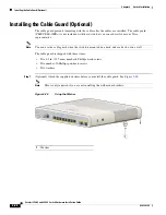
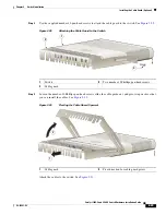
Page 54: ...representative Note You can use the cable guard when the switch is mounted on a desk under a desk or on a wall The cable guard is shipped with these items Two 0 5 in 12 7 mm number 8 Phillips wood screws Two number 10 Phillips pan head screws Two washers Step 1 Optional Attach the supplied washers before you install the cable guard See Figure 2 28 Note This is only required if you are not installi...

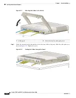
Page 55: ...lips pan head screws slide the cable guide out and pivot it upwards so that you can install the cables See Figure 2 30 Figure 2 30 Pivoting the Cable Guard Upwards Attach the cables to the switch See Figure 2 31 1 Switch 3 Two number 10 Phillips pan head screws 2 Cable guard MODE CONSOLE 1 2 Catalyst 2960 C Series PD POWER OVER ETHERNET 1 2 3 4 5 6 7 8 PD SPD PoE DPLX STAT SYST 208916 2 1 3 1 Cabl...

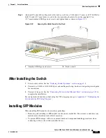
Page 56: ... Switch Step 4 Guide the connected cables through the slots in the front of the cable guard Slide the cable guide in as shown in Figure 2 33 Tighten the screws Figure 2 32 Guiding the Cables through the Guard 1 Cable guard 2 Pivot direction for cable guard pivots MODE CONSOLE 1 2 Catalyst 2960 C Series PD POWER OVER ETHERNET 1 2 3 4 5 6 7 8 PD SPD PoE DPLX STAT SYST 208918 1 2 330040 ...

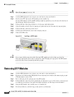
Page 57: ...ct to a 10 100 or 10 100 1000 port and run Express Setup See the switch getting started guide for instructions 3 Connect to the ports See the Connecting Devices to the Ethernet Ports section on page 2 33 to complete the installation For configuration instructions about using the CLI setup program go to Appendix C Configuring the Switch with the CLI Setup Program Installing SFP Modules When install...

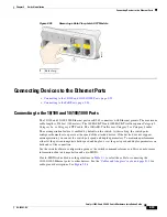
Page 58: ...s Figure 2 34 Installing an SFP Module Caution Do not remove the dust plugs from the fiber optic SFP module port or the rubber caps from the fiber optic cable until you are ready to connect the cable The plugs and caps protect the SFP module ports and cables from contamination and ambient light Removing SFP Modules Step 1 Attach an ESD preventive wrist strap to your wrist and to a bare metal surfa...

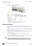
Page 59: ... The autonegotiation feature is enabled by default on the switch At this setting the switch ports configure themselves to operate at the speed of the attached device If the device does not support autonegotiation you can set the switch port speed and duplex parameters To maximize performance either let the ports autonegotiate both speed and duplex or set the port speed and duplex parameters on bot...

Page 60: ...ccess point To access an advanced PoE planning tool use the Cisco Power Calculator on Cisco com http tools cisco com 20 launch jsp You can use this application to calculate the power supply requirements for a specific PoE configuration The results show output current output power and heat dissipation Warning Voltages that present a shock hazard may exist on Power over Ethernet PoE circuits if inte...

Page 61: ... area can be accessed only through the use of a special tool lock and key or other means of security Statement 1072 Caution Category 5e and Category 6 cables can store high levels of static electricity Always ground the cables to a suitable and safe earth ground before connecting them to the switch or other devices Where to Go Next To change the switch settings you can use the switch default confi...

Page 62: ...2 36 Catalyst 3560 C and 2960 C Switch Hardware Installation Guide OL 23803 02 Chapter 2 Switch Installation Where to Go Next ...

Page 63: ...res port connectivity problems and overall switch performance You can also get statistics from the device manager the CLI or an SNMP workstation See the software configuration guide the switch command reference guide on Cisco com or the documentation that came with your SNMP application for details Switch POST Results See the Verifying Switch Operation section on page 2 5 for information on POST N...

Page 64: ...le For Ethernet use Category 3 copper cable for 10 Mb s UTP connections Use either Category 5 Category 5e or Category 6 UTP for 10 100 or 10 100 1000 Mb s connections Verify that you have the correct fiber optic cable for the distance and port type Make sure that the connected device ports match and use the same type encoding optical frequency and fiber type Determine if a copper crossover cable w...

Page 65: ...ing to connect Cisco prestandard IP Phones and wireless access points or 802 3af compliant devices SFP Module Use only Cisco SFP modules Each Cisco module has an internal serial EEPROM that is encoded with security information This encoding verifies that the module meets the requirements for the switch Inspect the SFP module Exchange the suspect module with a known good module Verify that the modu...

Page 66: ... happen when manually setting the speed and duplex or from autonegotiation issues between the two devices To maximize switch performance and to ensure a link follow one of these guidelines when changing the duplex or the speed settings Let both ports autonegotiate both speed and duplex Manually set the speed and duplex parameters for the interfaces on both ends of the connection If a remote device...

Page 67: ...figuring the Switch with the CLI Setup Program Alternatively you can press the Reset button on the rear of the switch to power cycle the switch Finding the Switch Serial Number If you contact Cisco Technical Assistance you need to know the switch serial number Figure 3 1 and Figure 3 2 show the serial number locations You can also use the show version privileged EXEC command to see the switch seri...

Page 68: ... 3560CG 8PC S 3560CG 8PC S and the 3560CG 8TC S Figure 3 3 Serial Number Location for the Catalyst 3560CPD 8PT S Switch MO DE SPD PoE DPL X STA T SYS T 1 2 3 4 5 6 7 8 2 1 CO NSO LE PO WE R OVE R ETH ERN ET 9 9 Se rie s Po E SN XXXNNNNXXXX 208982 MO DE SPD PoE DPL X STA T SYS T Ca tal ys t 35 60 C G Se rie s PD 1 2 3 4 5 6 7 8 2 1 CO NSO LE PO WE R OVE R ETH ERN ET SN XXXNNNNXXXX 209218 ...

Page 69: ...Serial Number Location for the Catalyst 2960C 8TC L 2960C 8TC S 2960C 8PC L 2960C 12PC L 3560C 8PC S and 3560C 12PC S Switches E SPD PoE DPL X STA T SYS T 1 2 3 4 5 6 7 8 2 1 CO NSO LE 1 2 1 1 MO DE Ca tal yst 396 0 C Ser ies Po E SPD PoE DPL X STAT SYST 1 2 3 4 5 7 9 11 CON SOL E POW ER OVER ETH ERN ET 6 8 10 12 SN XXXNNNNXXXX 330039 781 00727 01 ...

Page 70: ...3 8 Catalyst 3560 C and 2960 C Switch Hardware Installation Guide OL 23803 02 Chapter 3 Troubleshooting Finding the Switch Serial Number ...

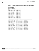
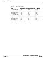
Page 71: ...PD 8PT L Catalyst 2960C 8TC L Catalyst 2960C 8TC S Catalyst 2960C 8PC L Catalyst 2960C 12PC L Catalyst 3560C 8PC S Catalyst 3560C 12PC S 23 to 113 F 5 to 45 C up to 5000 ft 1524 m Catalyst 2960CG 8TC L Catalyst 3560CG 8PC S Catalyst 3560CG 8TC S Catalyst 3560CPD 8PT S 23 to 104 F 5 to 40 C up to 5000 ft 1524 m Storage temperature 22 to 158 F 30 to 70 C up to 15 000 ft 4573 m Relative humidity 5 to...

Page 72: ...CPD 8PT L Catalyst 2960CG 8TC L Catalyst 2960C 8TC L Catalyst 2960C 8TC S Catalyst 2960C 8PC L Catalyst 2960C 12PC L Catalyst 3560CG 8PC S Catalyst 3560CG 8TC S Catalyst 3560CPD 8PT S Catalyst 3560C 8PC S Catalyst 3560C 12PC S 1 75 x 6 8 x 10 6 in 4 4 x 17 2 x 26 9 cm 1 75 x 6 8 x 10 6 in 4 4 x 17 2 x 26 9 cm 1 75 x 8 4 x 10 6 in 4 4 x 21 3 x 26 9 cm 1 75 x 8 4 x 10 6 in 4 4 x 21 3 x 26 9 cm 1 75 ...

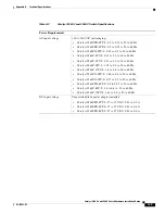
Page 73: ... to 0 1 A 50 to 60 Hz Catalyst 2960C 8TC S 0 21 to 0 1 A 50 to 60 Hz Catalyst 2960C 8PC L 1 59 to 0 8 A 50 to 60 Hz Catalyst 2960C 12PC L 1 6 to 0 8 A 50 to 60 Hz Catalyst 3560CG 8PC S 1 68 to 0 8 A 50 to 60 Hz Catalyst 3560CG 8TC S 0 37 to 0 2 A 50 to 60 Hz Catalyst 3560CPD 8PT S 0 5 to 0 25 A 50 to 60 Hz Catalyst 3560C 8PC S 1 6 to 0 8 A 50 to 60 Hz Catalyst 3560C 12PC S 1 61 to 0 8 A 50 to 60 H...

Page 74: ...atalyst 3560CG 8TC S 19 6 W 67 BTUs per hour Catalyst 3560CPD 8PT S 41 1 W 88 BTUs per hour AC 40 W 84 BTUs per hour DC PD Catalyst 3560C 8PC S 158 W 74 BTUs per hour Catalyst 3560C 12PC S 159 W 85 BTUs per hour Power rating Catalyst 2960CPD 8TT L 0 02 KVA Catalyst 2960CPD 8PT L 0 05 KVA Catalyst 2960CG 8TC L 0 04 KVA Catalyst 2960C 8TC L 0 03 KVA Catalyst 2960C 8TC S 0 03 KVA Catalyst 2960C 8PC L...

Page 75: ... 14 5 W 43 W1 51 W2 22 4 W1 30 82 1 Requires both the uplink ports to be connected to PoE inputs 2 Reguires the uplink port to be connected to Cisco UPOE switch input Catalyst 2960C 8PC L 17 1 W 157 W 123 2 W Catalyst 2960C 12PC L 18 6 W 158 W 123 2 W Catalyst 3560CPD 8PT S 21 7 W 40 W1 51 W2 15 4 W1 23 82 Catalyst 3560CG 8PC S 23 9 W 158 W 123 2 W Catalyst 3560C 8PC S 17 3 W 158 W 123 2 W Catalys...

Page 76: ...A 6 Catalyst 3560 C and 2960 C Switch Hardware Installation Guide OL 23803 02 Appendix A Technical Specifications ...

Page 77: ...10 100 and 10 100 1000 Ports page B 1 SFP Module Connectors page B 2 Dual Purpose Ports page B 2 Cables and Adapters page B 3 10 100 and 10 100 1000 Ports The 10 100 and 10 100 1000 Ethernet ports on switches use RJ 45 connectors and Ethernet pinouts with internal crossovers Figure B 1 and Figure B 2 show the pinouts Figure B 1 10 100 Port Pinouts H5318 2 3 1 4 5 6 7 8 Pin Label 1 2 3 4 5 6 7 8 RD...

Page 78: ...g Invisible laser radiation may be emitted from disconnected fibers or connectors Do not stare into beams or view directly with optical instruments Statement 1051 Dual Purpose Ports The 10 100 1000 Ethernet ports on the dual purpose ports use RJ 45 connectors Figure B 4 10 100 1000 Port Pinouts 60915 2 3 1 4 5 6 7 8 Pin Label 1 2 3 4 5 6 7 8 TP0 TP0 TP1 TP2 TP2 TP1 TP3 TP3 58476 60915 2 3 1 4 5 6 ...

Page 79: ... link distance can cause transceiver saturation resulting in an elevated bit error rate BER When using the LX LH SFP module with 62 5 micron diameter MMF you must also install a mode conditioning patch cord between the SFP module and the MMF cable on both the sending and receiving ends of the link The mode conditioning patch cord is required for link distances greater than 984 feet 300 m 62 5 125 ...

Page 80: ...Two Twisted Pair Crossover Cable Schematic for 10 100 Ports Figure B 7 Four Twisted Pair Straight Through Cable Schematic for 1000BASE T Ports 3 1000BASE ZX SFP modules can send data up to 62 miles 100 km by using dispersion shifted SMF or low attenuation SMF the distance depends on the fiber quality the number of splices and the connectors 4 A mode field diameter cladding diameter 9 micrometers 1...

Page 81: ...ctor which is described in Table B 2 and Table B 3 If you did not order a console cable you need to provide an RJ 45 to DB 9 adapter cable to connect the switch console port to a PC console port You need to provide an RJ 45 to DB 25 female DTE adapter if you want to connect the switch console port to a terminal You can order an adapter part number ACS DSBUASYN For console port and adapter pinout i...

Page 82: ... supplied with the switch You can order this adapter from Cisco part number ACS DSBUASYN TxD 2 RxD GND 5 GND RxD 3 TxD DSR 4 DTR CTS 7 RTS Table B 2 Console Port Signaling Using a DB 9 Adapter continued Switch Console Port DTE RJ 45 to DB 9 Terminal Adapter Console Device Signal DB 9 Pin Signal Table B 3 Console Port Signaling Using a DB 25 Adapter Switch Console Port DTE RJ 45 to DB 25 Adapter Co...

Page 83: ...ings in Chapter 2 Switch Installation Accessing the CLI Through the Console Port You can enter Cisco IOS commands and parameters through the CLI Use one of these options to access the CLI RJ 45 Console Port USB Mini Type B Console Port RJ 45 Console Port Step 1 Connect the RJ 45 to DB 9 adapter cable to the 9 pin serial port on the PC Connect the other end of the cable to the switch console port S...

Page 84: ...aracteristics 9600 baud 8 data bits 1 stop bit No parity None flow control Step 4 Connect power to the switch as described in Chapter 2 Switch Installation Step 5 The PC or terminal displays the bootloader sequence Press Enter to display the setup prompt Follow the steps in the Completing the Setup Program section on page C 7 1 RJ 45 console port 2 Console cable RJ 45 to DB 9 adapter cable M O DE ...

Page 85: ...Windows Vista and Windows 7 USB Driver section on page C 5 Figure C 2 Connecting the USB Mini Console Cable Step 2 Connect an USB cable to the PC USB port Connect the other end of the cable to the switch mini B 5 pin connector USB mini console port See Figure C 2 Step 3 To identify the COM port assigned to the USB mini console port Choose Start Control Panel Systems Click the Hardware tab and choo...

Page 86: ... to display the setup prompt Follow the steps in the Completing the Setup Program section on page C 7 Installing the Cisco Microsoft Windows USB Device Drivers Installing the Cisco Microsoft Windows XP USB Driver Step 1 Obtain the file Cisco_usbconsole_driver zip from Cisco com and unzip it Note You can download the driver file from the Cisco com software download site Step 2 If using 32 bit Windo...

Page 87: ...ollow the instructions to complete the driver installation Installing the Cisco Microsoft Windows Vista and Windows 7 USB Driver Step 1 Obtain the file Cisco_usbconsole_driver zip from Cisco com and unzip it Note You can download the driver file from the Cisco com software download site Step 2 If using 32 bit Windows Vista or Windows 7 double click the setup exe file in the Windows_32 folder If us...

Page 88: ...utton Click Next Using the Setup exe Program Note Disconnect the switch console terminal before uninstalling the driver Step 1 Run setup exe for 32 bit Windows or setup x64 exe for 64 bit Windows Click Next Step 2 The InstallShield Wizard for Cisco Virtual Com appears Click Next Step 3 When the Program Maintenance window appears click the Select the radio button Click Next Step 4 When the Remove t...

Page 89: ...Subnet mask IP netmask Default gateway router Enable secret password Enable password Telnet password Completing the Setup Program Follow these steps to complete the setup program and to create an initial configuration for the switch Step 1 Enter Yes at these two prompts Would you like to enter the initial configuration dialog yes no yes At any point you may enter a question mark for help Use ctrl ...

Page 90: ...ce that connects to the management network and press Return For this release always use vlan1 as that interface Enter interface name used to connect to the management network from the above interface summary vlan1 Step 8 Configure the interface by entering the switch IP address and subnet mask and pressing Return The IP address and subnet masks shown below are examples Configuring interface vlan1 ...

Page 91: ...and prompt without saving this config 1 Return back to the setup without saving this config 2 Save this configuration to nvram and exit If you want to save the configuration and use it the next time the switch reboots select option 2 to save it in NVRAM Enter your selection 2 2 Make your selection and press Return After you complete the setup program the switch can run the default configuration th...

Page 92: ...C 10 Catalyst 3560 C and 2960 C Switch Hardware Installation Guide OL 23803 02 Appendix C Configuring the Switch with the CLI Setup Program Entering the Initial Configuration Information ...

Reviews: