background image

B-3

Cisco 2600 Series Routers Hardware Installation Guide

OL-2171-02

Appendix B      Maintaining the Router

Accessing the System Board

Warning

Before opening the chassis, disconnect the telephone-network cables to avoid contact with 
telephone-network voltages. To see translations of the various warnings that appear in this 
publication, refer to the 

Regulatory Compliance and Safety Information

 document that 

accompanied this device.

Step 3

Attach an ESD-preventive wrist strap and ensure that it makes good contact with your skin. Connect the 
equipment end of the wrist strap to the metal back plate of the chassis.

Step 4

Remove the screws located on the top of the chassis. Note that the chassis is comprised of two sections: 
top and bottom.

Step 5

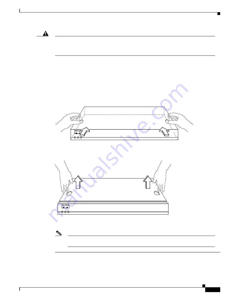
Holding the chassis with both hands, position it as shown in 

Figure B-1

.

Step 6

Slide the top section away from the bottom section as shown in 

Figure B-2

.

Figure B-1

Holding Chassis for Cover Removal

Figure B-2

Removing Chassis Cover

Step 7

When the top cover is off, set it aside.  

Figure B-5

 shows the layout of the system board.

Note

The system board layout in 

Figure B-5

 shows the boot ROM in position U22. On the 

Cisco 261x, the boot ROM is in position U23.

POWER

RPS

ACTIVITY

H11658

Cisco 2600

SERIES

35392

POWER

RPS

ACTIVITY

Cisco 2600

SERIES

Summary of Contents for 2600 Series

Page 1: ...rs Cisco Systems Inc 170 West Tasman Drive San Jose CA 95134 1706 USA http www cisco com Tel 408 526 4000 800 553 NETS 6387 Fax 408 526 4100 Cisco 2600 Series Routers Hardware Installation Guide Text Part Number OL 2171 02 ...

Page 2: ...evision or radio antenna until the interference stops Move the equipment to one side or the other of the television or radio Move the equipment farther away from the television or radio Plug the equipment into an outlet that is on a different circuit from the television or radio That is make certain the equipment and the television or radio are on circuits controlled by different circuit breakers ...

Page 3: ...iii Cisco com xiii Technical Assistance Center xiii Cisco TAC Web Site xiv Cisco TAC Escalation Center xiv C H A P T E R 1 Overview of Cisco 2600 Series Routers 1 1 Hardware Features 1 2 Module Interface Information 1 3 System Specifications 1 3 Regulatory Compliance 1 5 C H A P T E R 2 Preparing to Install the Router 2 1 Safety Recommendations 2 1 Safety Warnings 2 1 Maintaining Safety with Elect...

Page 4: ...kbps DSU CSU Connections 2 13 C H A P T E R 3 Installing the Router 3 1 Required Tools and Equipment 3 1 Setting Up the Chassis 3 2 Setting the Chassis on a Desktop 3 2 Mounting the Chassis in a Rack 3 4 Attaching the Brackets to Cisco 261x Cisco 262x Cisco 26xxXM and Cisco 265x Series Routers 3 5 Attaching the Brackets to a Cisco 2691 Router 3 9 Installing the Router in a Rack 3 10 Mounting the C...

Page 5: ...1x Cisco 262x Cisco 265x and Cisco 26xxXM B 2 Tools Required B 2 Removing the Chassis Cover B 2 Removing the Chassis Cover on Cisco 2691 B 4 Upgrading DRAM B 5 Memory Capacities B 6 Cisco 261x Cisco 262x Cisco 265x and Cisco 26xxXM B 6 Cisco 2691 B 10 SDRAM DIMM Orientation B 11 Removing SDRAM DIMMS B 12 Installing SDRAM DIMMs B 13 Replacing Flash Memory B 14 Cisco 261x Cisco 262x Cisco 265x and C...

Page 6: ...sh File System B 26 File Operations B 26 Replacing the Boot ROM B 29 Cisco 261x Cisco 262x Cisco 265x and Cisco 26xxXM Routers B 29 Testing ROM Installation B 33 Cisco 2691 B 33 Closing the Chassis B 34 Replacing the Chassis Cover on Cisco 261x Cisco 262x Cisco 265x and Cisco 26xxXM B 34 Replacing the Chassis Cover on Cisco 2691 B 35 Replacing the Power Supply B 36 A P P E N D I X C Using the ROM ...

Page 7: ... 2611XM Cisco 2612 and Cisco 2613 Cisco 2620 and Cisco 2620XM Cisco 2621 and Cisco 2621XM Cisco 2650 and Cisco 2650XM Cisco 2651 and Cisco 2651XM Cisco 2691 Although this document provides minimum software configuration information it is not comprehensive For detailed software configuration information refer to the Cisco IOS configuration guide and command reference publications These publications...

Page 8: ...rk Module or Interface Card Discusses network module and WAN and voice interface card installation Appendix A Troubleshooting the Router Discusses how to isolate problems and read the LEDs Appendix B Maintaining the Router Discusses selected maintenance procedures Appendix C Using the ROM Monitor Describes the ROM monitor also called the bootstrap program Use the ROM monitor to help you isolate or...

Page 9: ...r U verkeert in een situatie die lichamelijk letsel kan veroorzaken Voordat u aan enige apparatuur gaat werken dient u zich bewust te zijn van de bij elektrische schakelingen betrokken risico s en dient u op de hoogte te zijn van standaard maatregelen om ongelukken te voorkomen Voor vertalingen van de waarschuwingen die in deze publicatie verschijnen kunt u het document Regulatory Compliance and S...

Page 10: ...e som finnes i denne publikasjonen kan du se i dokumentet Regulatory Compliance and Safety Information Overholdelse av forskrifter og sikkerhetsinformasjon som ble levert med denne enheten Aviso Este símbolo de aviso indica perigo Encontra se numa situação que lhe poderá causar danos físicos Antes de começar a trabalhar com qualquer equipamento familiarize se com os perigos relacionados com circui...

Page 11: ...Start Guide Cisco Modular Access Router Cable Specifications Cisco Redundant Power System Hardware Installation Guide Cisco Network Modules Hardware Installation Guide Cisco WAN Interface Cards Hardware Installation Guide Software Configuration Guide for Cisco 3600 Series and Cisco 2600 Series Routers Regulatory Compliance and Safety Information Installing the Cisco 2600 Series NEBS Level 3 ETSI C...

Page 12: ...through an annual subscription Ordering Documentation Cisco documentation is available in the following ways Registered Cisco Direct Customers can order Cisco product documentation from the Networking Products MarketPlace http www cisco com cgi bin order order_root pl Registered Cisco com users can order the Documentation CD ROM through the online Subscription Store http www cisco com go subscript...

Page 13: ...world Cisco com is a highly integrated Internet application and a powerful easy to use tool that provides a broad range of features and services to help you to Streamline business processes and improve productivity Resolve technical issues with online support Download and test software packages Order Cisco learning materials and merchandise Register for online skill assessment training and certifi...

Page 14: ...service contract but do not have a login ID or password go to the following URL to register http www cisco com register If you cannot resolve your technical issues by using the Cisco TAC Web Site and you are a Cisco com registered user you can open a case online by using the TAC Case Open tool at the following URL http www cisco com tac caseopen If you have Internet access it is recommended that y...

Page 15: ...d as well as the system specifications See Table 1 2 Table 1 1 Summary of Cisco 2600 Series LAN Interfaces Model Ethernet 10BASE T Token Ring RJ 45 Fast Ethernet 10 100 Network Module Slot WAN Interface Card Slots Advanced Integration Module Slots Cisco 2610 1 1 2 1 Cisco 2610XM 1 1 2 1 Cisco 2611 2 1 2 1 Cisco 2611XM 2 1 2 1 Cisco 2612 1 1 1 2 1 Cisco 2613 1 1 2 1 Cisco 2620 1 1 2 1 Cisco 2620XM ...

Page 16: ...IA TIA 232 RJ 45 console port for local system access by using a console terminal EIA TIA 232 RJ 45 auxiliary port for remote system access or dial backup by using a modem Figure 1 1 and Figure 1 2 show examples of Cisco 2600 series routers Note Cisco 2600 series routers are either single rack unit 1RU or two rack unit 2RU high Note The number and type of interfaces will vary depending on the spec...

Page 17: ...nstallation For information about installing Advanced Interface Modules go to Cisco Product Documentation Access Servers and Access Routers Modular Access Routers Cisco 2600 Routers Hardware installation documents for Cisco 2600 series Advanced interface module AIM installation System Specifications 72056 SEE MANUAL BEFORE INSTALLATION AL CD LP RD TD SEE MANUAL BEFORE INSTALLATION DSU 56K AL CD LP...

Page 18: ...nadian DOC Class A For more regulatory information refer to the Regulatory Compliance and Safety Information document that accompanied your router 1 Btus British thermal units Table 1 3 Cisco 2691 System Specifications Description Specification Dimensions H x W x D 3 46 x 17 07 x 11 20 in 8 78 x 45 36 x 28 45 cm two rack unit in height Weight 15 lb 6 80 kg Input voltage AC power supply Current emi...

Page 19: ... Safety Information document that accompanied this device Noise level 45 dBA maximum Regulatory compliance FCC Part 15 Class A For additional compliance information refer to the Regulatory Compliance and Safety Information document that accompanied the router Safety compliance UL 60950 CAN CSA C22 2 No 60950 00 IEC 60950 EN 60950 AS NZS 3260 TS001 Table 1 3 Cisco 2691 System Specifications continu...

Page 20: ...1 6 Cisco 2600 Series Routers Hardware Installation Guide OL 2171 02 Chapter 1 Overview of Cisco 2600 Series Routers Regulatory Compliance ...

Page 21: ...d chassis cover in a safe place Keep tools away from walk areas where you and others could fall over them Do not wear loose clothing that could get caught in the chassis Fasten your tie or scarf and roll up your sleeves Wear safety glasses if you are working under any conditions that might be hazardous to your eyes Do not perform any action that creates a potential hazard to people or makes the eq...

Page 22: ...hen working on equipment powered by electricity Warning Before working on equipment that is connected to power lines remove jewelry including rings necklaces and watches Metal objects will heat up when connected to power and ground and can cause serious burns or can weld the metal object to the terminals To see translations of the warnings that appear in this publication refer to the Regulatory Co...

Page 23: ... the system If possible send another person to get medical aid Otherwise assess the condition of the victim and then call for help Determine if the victim needs rescue breathing or external cardiac compressions then take appropriate action Preventing Electrostatic Discharge Damage Electrostatic discharge ESD can damage equipment and impair electrical circuitry It occurs when electronic components ...

Page 24: ...ge section on page 23 to avoid damage to equipment Damage from static discharge can cause immediate or intermittent equipment failure Ensure that the chassis cover is secure The chassis is designed to allow cooling air to flow effectively inside it An open chassis allows air leaks which might interrupt and redirect the flow of cooling air from internal components Configuring Equipment Racks The fo...

Page 25: ...circuit breaker no larger than 120 VAC 15A U S 240 VAC 10A international is used on the phase conductors all current carrying conductors To see translations of the warnings that appear in this publication refer to the Regulatory Compliance and Safety Information document that accompanied this device Preparing to Connect to a Network When setting up your router consider distance limitations and pot...

Page 26: ... Token Ring Connections The Cisco 2612 provides both an Ethernet interface and a Token Ring shielded UTP interface The Cisco 2613 provides a single Token Ring interface See Table 2 1 The IEEE has established Token Ring as standard IEEE 802 5 Specifications indicate a maximum segment distance of 328 feet 100 meters for UTP cabling Note To ensure agency compliance with FCC Class B electromagnetic em...

Page 27: ...Cisco 2600 Routers Hardware installation documents for Cisco 2600 series Interface card installation For information about installing network modules refer to the Cisco Network Modules Hardware Installation Guide located at Cisco Product Documentation Access Servers and Access Routers Modular Access Routers Cisco 2600 Routers Hardware installation documents for Cisco 2600 series Network module net...

Page 28: ...ing from a CSU DSU or other DCE device Although manufacturing your own serial cables is not recommended because of the small size of the pins on the DB 60 serial connector cable pinouts are provided in the Cisco Modular Access Router Cabling Specifications document on Cisco com and the Documentation CD ROM that accompanied your router Distance Limitations Serial signals can travel a limited distan...

Page 29: ...supports unbalanced circuits at signal speeds up to 64 kbps The network end of the adapter cable is a standard 25 pin D shell connector known as a DB 25 See Figure 2 1 The router console and auxiliary ports also use EIA TIA 232 connections however the serial module ports support synchronous connections and the console and auxiliary ports support asynchronous connections Figure 2 1 EIA TIA 232 Adap...

Page 30: ...e Connectors Network End V 35 Connections The V 35 interface is recommended for speeds up to 48 kbps although it is often used successfully at 4 Mbps The network end of the V 35 adapter cable provides a standard 34 pin Winchester type connector See Figure 2 3 V 35 cables are available with a standard V 35 plug or receptacle in either DTE or DCE mode Figure 2 3 V 35 Adapter Cable Connectors Network...

Page 31: ...ectrical specifications of EIA TIA 422 and EIA TIA 423 Although the specification recommends a maximum speed of 2 Mbps EIA 530 is used successfully at 4 Mbps or faster over short distances The EIA TIA 530 adapter cable is available in DTE mode only The network end of the EIA 530 adapter cable is a standard DB 25 plug commonly used for EIA TIA 232 connections Figure 2 5 shows the DB 25 connector at...

Page 32: ...work hazardous voltages also are present on the system card in the area of the BRI port RJ 45 connector regardless of when power is turned OFF To see translations of the warnings that appear in this publication refer to the Regulatory Compliance and Safety Information document that accompanied this device Warning The ISDN connection is regarded as a source of voltage that should be inaccessible to...

Page 33: ...ss Routers Cisco 2600 Routers Hardware installation documents for Cisco 2600 series Interface card installation 56K Switched 56 kbps DSU CSU Connections Switched 56 kbps connections are provided by the 56 kbps DSU CSU WAN interface card For more information on Switched 56 kbps WAN interface cards refer to the Cisco WAN Interface Cards Hardware Installation Guide located at Cisco Product Documentat...

Page 34: ...2 14 Cisco 2600 Series Routers Hardware Installation Guide OL 2171 02 Chapter 2 Preparing to Install the Router Preparing to Connect to a Network ...

Page 35: ...on refer to the Regulatory Compliance and Safety Information document that accompanied this device Required Tools and Equipment Installation might require some tools and equipment that are not provided as standard equipment with the router Following are the tools and parts required for a typical router installation Number 2 Phillips screwdriver Flat blade screwdrivers small 3 16 in 0 476 cm and me...

Page 36: ...ons on connecting a console terminal Modem for connection to the auxiliary port for remote administrative access Optional Setting Up the Chassis You can set the chassis on a desktop install it in a rack or mount it on a wall or other flat surface Use the procedure in this section that best meets the needs of your network The sections are as follows Setting the Chassis on a Desktop page 3 2 Mountin...

Page 37: ...outer upside down on a smooth flat surface Step 3 Peel off the rubber feet from the black adhesive strip and place them adhesive side down onto the five round recessed areas on the bottom of the chassis See Figure 3 2 and Figure 3 3 Figure 3 2 Rubber Feet Location on Cisco 261x Cisco 262x Cisco 26xxXM and Cisco 265x Series Routers Rubber feet 5 Black adhesive strip H4796 Fan H4795 ...

Page 38: ...ptional larger brackets for use with a 23 or 24 inch rack Cisco 2600 series routers with a chassis height of 2 rack units 2RU ship with brackets for use with a 19 inch rack The brackets are shown in Figure 3 4 and Figure 3 5 Warning To prevent bodily injury when mounting or servicing this unit in a rack you must take special precautions to ensure that the system remains stable To see translations ...

Page 39: ...8 and Figure 3 9 In a center mount rack with the rear panel forward see Figure 3 10 through Figure 3 12 Note Use the screws that came with your router package for attaching the brackets Note If you are installing a Cisco 2600 series router in a 19 inch rack with a 17 5 inch opening orient the rack mount brackets so that when installed they do not increase the width of the chassis See Figure 3 6 If...

Page 40: ...ront Panel Forward 19 Inch Rack with a 17 5 Inch Opening Note When installed in a 19 inch rack with a 17 75 inch opening the Cisco 2600 series routers will protrude beyond the front of the rack Figure 3 7 Bracket Installation Front Panel Forward 19 Inch Rack with a 17 75 Inch Opening or a 23 or 24 Inch Rack 62676 Note The second bracket attaches to the other side of the chassis 62881 Note The seco...

Page 41: ... Inch Opening Figure 3 9 Bracket Installation Rear Panel Forward 19 Inch Rack with a 17 75 Inch Opening or a 23 or 24 Inch Rack 72013 Note The second bracket attaches to the other side of the chassis Brackets for 19 inch rack 110V 60 Hz 1 6A MAX 72014 Note The second bracket attaches to the other side of the chassis 110V 60 Hz 1 6A MAX Brackets for 19 inch rack Brackets for 23 inch or 24 inch rack...

Page 42: ...ack Figure 3 12 Center Mount Bracket Installation Front Panel Forward 19 Inch Rack with a 17 5 Inch Opening or a 23 or 24 Inch Rack 72015 Note The second bracket attaches to the other side of the chassis 110V 60 Hz 1 6A MAX Brackets for 19 inch rack Brackets for 23 inch or 24 inch rack 62983 Note The second bracket attaches to the other side of the chassis Brackets for 19 inch rack Brackets for 23...

Page 43: ...ews that came with your router package for attaching the brackets Figure 3 13 Bracket Installation Front Panel Forward 19 Inch Rack Figure 3 14 Bracket Installation Rear Panel Forward 19 Inch Rack LEFT Wide bracket marked RIGHT 62103 Narrow bracket marked LEFT RIGHT SERIES SERIES RIGHT Wide bracket marked RIGHT 62109 SEE MANUA L BEFORE INSTALLATION Narrow bracket marked LEFT AL CD LP RD TD SEE MAN...

Page 44: ...allation Rear Panel Forward 19 Inch Rack Installing the Router in a Rack After the brackets are secured to the chassis you can mount the chassis in a rack Use the illustrations in the previous section as a guide to attaching the brackets to the rack Note The screws for attaching the brackets to the rack are not included with the router Caution Always use two screws to attach each bracket to the ra...

Page 45: ...he chassis Step 1 Attach the brackets as shown in Figure 3 17 Figure 3 17 Attaching the Wall Mount Brackets Step 2 Attach the chassis assembly to the wall as shown in Figure 3 18 using screws and anchors that you provide We recommend the following For the best support of the chassis and cables attach the brackets so that the screws align with a vertical wall stud See Figure 3 18 This position will...

Page 46: ...cted access areas A restricted access area is where access can only be gained by service personnel through the use of a special tool lock and key or other means of security and is controlled by the authority responsible for the location To see translations of the warnings that appear in this publication refer to the Regulatory Compliance and Safety Information document that accompanied this device...

Page 47: ...at all power is OFF locate the circuit breaker on the panel board that services the DC circuit switch the circuit breaker to the OFF position and tape the switch handle of the circuit breaker in the OFF position To see translations of the warnings that appear in this publication refer to the Regulatory Compliance and Safety Information document that accompanied this device Step 1 Using 14 AWG copp...

Page 48: ...nto the slotted wire receptacles on the terminal block See Figure 3 20 Warning The illustration shows the DC power supply terminal block The proper wiring sequence is ground to ground positive to positive line to L and negative to negative neutral to N Note that the ground wire should always be connected first and disconnected last To see translations of the warnings that appear in this publicatio...

Page 49: ... supply remove the tape from the circuit breaker switch handle and reinstate power by moving the handle of the circuit breaker to the ON position Grounding the Chassis Warning Units must have a permanent ground connection in addition to the power ground wire A grounding lug must be installed to ensure proper electrical protection Follow this procedure to attach the grounding lug to your router cha...

Page 50: ...n 20 mm Step 3 Crimp the grounding lug around the wire See Figure 3 21 Figure 3 21 Crimping the Lug Around the Wire Step 4 Use the number 2 Phillips screwdriver to fasten the grounding lug to the chassis See Figure 3 22 or Figure 3 23 Figure 3 22 Attaching the Grounding Lug on Cisco 261x Cisco 262x Cisco 26xxXM and Cisco 265x Routers 10360 36453 SEE MANUAL BEFORE INSTALLATION SERIAL 1 SERIAL 0 CON...

Page 51: ...panel is on Connecting to a Network Connecting to a LAN This section explains how to use the Ethernet and or Token Ring ports to connect the router to the LAN The basic Ethernet and Token Ring cables required to connect the router to a network are provided with the router See Table 3 1 For cable pinouts refer to the online document Cisco Modular Access Router Cabling Specifications on the Document...

Page 52: ...g protocol EIA TIA 232 EIA TIA 449 V 35 X 21 or EIA 530 and the serial port operating mode DTE or DCE See the Cisco Modular Access Router Cable Specifications for information about selecting these cables Cisco Smart serial Cisco Smart compact connector CSU DSU and serial network or equipment For WIC 2T and WIC 2A S only DSL RJ 11C CA11A lavender Network demarcation device for service provider s DS...

Page 53: ...0 60 Hz 47 W W0 AUX CONSOLE ETHERNET 0 ACT LINK ACT ETHERNET 1 LINK 10BASE T cable Ethernet 10BASE T port RJ 45 10BASE T hub or switch H11494 TX 1 2 3 4 5 6 7 8 9 10 11 12 13 14 15 16 17 18 19 20 PWR MODE RESET SYSREQ FAULT RX ATTACH STACK EIA 232 Catalyst 3900 RJ 11 twisted pair SEE MANUAL BEFORE INSTALLATION SERIAL 1 SERIAL 0 CONN CONN WIC 2A S SEE MANUAL BEFORE INSTALLATION SERIAL 1 SERIAL 0 CO...

Page 54: ...terminal or remotely with a modem Cisco provides cables and adapters to connect your router to a PC or modem These will include One RJ 45 console cable Blue One RJ 45 auxiliary cable Black One RJ 45 to DB 9 adapter Labeled TERMINAL One RJ 45 to DB 25 adapter Labeled MODEM or One RJ 45 to DB 9 adapter cable Blue One RJ 45 to DB 25 adapter cable Black Identifying a Rollover Cable Use a rollover cabl...

Page 55: ... a Console Terminal Step 2 Configure your terminal or PC terminal emulation software for 9600 baud 8 data bits no parity and 2 stop bits Note For information on console port pinouts refer to the online document Cisco Modular Access Router Cabling Specifications on Cisco com and the Documentation CD ROM that accompanied your router SEE MANUAL BEFORE INSTALLATION SERIAL 1 SERIAL 0 CONN CONN WIC 2A S...

Page 56: ... pinouts refer to the online document Cisco Modular Access Router Cabling Specifications on the Documentation CD ROM that accompanied your router package and on Cisco com What to Do After Installing Router Hardware After you have installed the router connect the power cable to the rear panel of the router and the power source and then power it ON If the router does not power on proceed to Appendix...

Page 57: ...ing a network module in a modular router chassis slot You can install network modules in the chassis either before or after mounting the router whichever is more convenient Warning Before installing a network module into the router chassis turn OFF electrical power to the router to avoid the risk of electrical shock to yourself or to the equipment To see translations of the warnings that appear in...

Page 58: ...or future use Step 5 Align the network module with the guides in the chassis and slide it gently into the slot Step 6 Slide the module into place until the edge connector is securely seated in the connector on the motherboard Step 7 Using the number 1 Phillips screwdriver tighten the module s captive mounting screws Step 8 Reinstall blank panels to fill any unoccupied chassis slots Caution To prov...

Page 59: ... presence of the WAN interface card in slot W1 if slot W0 is empty Step 5 Align the card with the guides in the module slot and gently slide it in Step 6 Push the card into place until the edge connector is seated in the connector on the module Step 7 Using a number 1 Phillips screwdriver tighten the captive mounting screws Step 8 Reinstall blank panels to fill any unoccupied module slots Caution ...

Page 60: ...f the circuit breaker in the OFF position Step 2 Remove all network cables including telephone cables from the rear panel of the router Step 3 Attach an ESD preventive wrist strap before handling the card and connect the wrist strap to an electrical ground Step 4 Using a number 1 Phillips screwdriver remove the blank filler panel from the voice module slot in the voice network module Save the blan...

Page 61: ...o 2610 and Cisco 2610XM Cisco 2611 and Cisco 2611XM Cisco 2612 and Cisco 2613 Cisco 2620 and Cisco 2620XM Cisco 2621 and Cisco 2621XM Cisco 2650 and Cisco 2650XM Cisco 2651 and Cisco 2651XM Cisco 2691 Isolating Problems The key to problem solving in this system is to try to isolate the problem to a specific subsystem By comparing what the system is doing to what it should be doing the task of isol...

Page 62: ... processor or the software or a DRAM single in line memory module SIMM might be installed incorrectly Troubleshooting the Ports Cables and Connections Check the following items to help isolate the problem If the router fails to recognize a port check the cable connection When the power switch is in the ON position make sure the power LED is on If not check the power source and power cable If the s...

Page 63: ...ing status Goes on when power is supplied to the router and the router is operational RPS Off No RPS1 is attached On RPS is attached and operational Blinking RPS is attached but has a failure 1 RPS Redundant Power System Activity Off In the Cisco IOS software but no network activity Blink 500 ms ON 500 ms OFF In ROMMON no errors Blink 500 ms ON 500 ms OFF 2 sec between codes In ROMMON error detect...

Page 64: ...depending on the router model Figure A 3 Cisco 2611 Rear Panel LEDs Table A 2 Cisco 2691 Front Panel LED Descriptions LED Description Power On Power is applied to the router SYS RPS Rapid blinking System is booting Slow blinking System error On System OK Activity Off No system activity Blinking System activity H11584 SEE MANUAL BEFORE INSTALLATION SERIAL 1 SERIAL 0 CONN CONN WIC 2A S SEE MANUAL BE...

Page 65: ...Cisco 2613 W0 AUX CONSOLE ACT TOKEN RING 0 0 LINK Token Ring 0 0 RJ 45 Link LED ACT LED Auxiliary port RJ 45 Console port RJ 45 14326 SEE MANUAL BEFORE INSTALLATION SERIAL 1 SERIAL 0 CONN CONN WIC 2A S SEE MANUAL BEFORE INSTALLATION SERIAL 1 SERIAL 0 CONN CONN WIC 2A S Cisco 2621 W0 W1 AUX CONSOLE 10 100 ETHERNET 0 0 10 100 ETHERNET 0 1 10 100BASE T Ethernet 0 0 RJ 45 10 100BASE T Ethernet 0 1 RJ ...

Page 66: ... Ethernet interface FDX When on the interface is in full duplex mode When off the interface is in half duplex mode 100 Mbps When on the speed of the interface is 100 Mbps When off the speed of the interface is 10 Mbps 31620 SEE MANUAL BEFORE INSTALLATION SERIAL 1 SERIAL 0 CONN CONN WIC 2A S SEE MANUAL BEFORE INSTALLATION SERIAL 1 SERIAL 0 CONN CONN WIC 2A S Cisco 2651 W0 W1 AUX CONSOLE 10 100 ETHE...

Page 67: ...received on the Ethernet interface 100 Mbps On when the speed of the interface is 100 Mbps Off when the speed of the interface is 10 Mbps CF1 On when the Flash device is being accessed either READ or WRITE 72011 SEE MANUAL BEFORE INSTALLATION CONSOLE AUX FAST ETHERNET 0 1 FAST ETHERNET 0 0 AL CD LP RD TD SEE MANUAL BEFORE INSTALLATION DSU 56K AL CD LP RD TD SEE MANUAL BEFORE INSTALLATION DSU 56K A...

Page 68: ...A 8 Cisco 2600 Series Routers Hardware Installation Guide OL 2171 02 Appendix A Troubleshooting the Router Reading the LEDs ...

Page 69: ...5 Replacing Flash Memory page B 14 Replacing the Boot ROM page B 29 Closing the Chassis page B 34 Replacing the Power Supply page B 36 Additional maintenance procedures are available on Cisco com and the Documentation CD ROM that shipped with your router Caution Before opening the chassis be sure that you have discharged all static electricity from your body and the power is OFF Before performing ...

Page 70: ...p the chassis underneath the lower edge and lift with both hands To prevent injury keep your back straight and lift with your legs not your back To prevent damage to the chassis and components never attempt to lift the chassis with the handles on the power supplies or on the interface processors or by the plastic panels on the front of the chassis These handles were not designed to support the wei...

Page 71: ...uipment end of the wrist strap to the metal back plate of the chassis Step 4 Remove the screws located on the top of the chassis Note that the chassis is comprised of two sections top and bottom Step 5 Holding the chassis with both hands position it as shown in Figure B 1 Step 6 Slide the top section away from the bottom section as shown in Figure B 2 Figure B 1 Holding Chassis for Cover Removal F...

Page 72: ...ct with telephone network voltages To see translations of the various warnings that appear in this publication refer to the Regulatory Compliance and Safety Information document that accompanied this device Step 3 Attach an ESD preventive wrist strap and ensure that it makes good contact with your skin Connect the equipment end of the wrist strap to the metal back plate of the chassis Step 4 Place...

Page 73: ...lease You are using very large routing tables or many protocols for example when the router is set up as part of both a large external network and your internal network To see how much memory is currently installed in the router enter the show version command Near the middle of the resulting output a message similar to the following appears Cisco 2610 MPC860 processor revision 0x200 with 28672K 40...

Page 74: ...e B 5 Each socket can be filled with a 100 pin DRAM DIMM EDO or SDRAM DIMMs depending on router model You can use the memory size iomem software command to configure DRAM as a mixture of shared memory which is used for data transmitted or received by network modules and WAN interface cards and primary or main memory which is reserved for the CPU For further information about this command refer to ...

Page 75: ... memory card For memory voltage requirements see Table B 1 To identify a 3 3V 100 pin SDRAM memory module look for the part number label on the front of the card See Figure B 4 Table B 2 and Table B 3 show the part numbers for the memory modules Figure B 4 Cisco 2600 Series 3 3 and 5V 100 Pin DRAM Module Table B 2 3 3V SDRAM Part Numbers Memory Size 3 3V SDRAM 32 MB 15 4108 xx 64 MB 15 4508 xx Tab...

Page 76: ...tep 4 Begin removing the existing DRAM DIMM by pulling outward on the connectors to unlatch them as shown in step 1 of part A in Figure B 6 Be careful not to break the holders on the DIMM connector Step 5 Remove the existing DRAM DIMM by pulling the module straight up as shown in step 2 of part A inFigure B 6 Caution To prevent damage do not press on the center of the DIMMs Handle each DIMM carefu...

Page 77: ... Step 7 Insert the new DRAM DIMM by sliding the end with the metal fingers into the DIMM connector socket at approximately a 90º angle to the system card Gently rock the DIMM back into place until the latch on either side snaps into place See steps 3 and 4 of part B in Figure B 6 Do not use excessive force because the connector might break Step 8 Replace the router cover Follow the instructions in...

Page 78: ...Near the middle of the resulting output a message similar to the following displays cisco 2691 R7000 processor revision 0 5 with 121856K 9216K bytes of memory This line shows how much memory is installed in this example 24576K 8192K The first number represents primary memory and the second number represents shared memory Your router supports up to 256 MB of SDRAM Each DIMM slot corresponds to one ...

Page 79: ... Figure B 8 shows the polarization notches and alignment holes on a DIMM Caution To avoid damaging ESD sensitive components observe all ESD precautions To avoid damaging the system board do not use excessive force when you remove or replace DIMMs Table B 4 SDRAM Configurations for Cisco 2691 Routers DIMM 0 DIMM 1 Total 64 MB DIMM 64 MB 128 MB DIMM 128 MB 64 MB DIMM 64 MB DIMM 128 MB 128 MB DIMM 12...

Page 80: ... with your skin Connect the equipment end of the wrist strap to the metal back plate of the chassis Step 2 On the system board locate the SDRAM DIMM sockets shown in Figure B 7 Caution Handle DIMMs by the edges only DIMMs are ESD sensitive components and can be damaged by mishandling Step 3 Remove the DIMM by pushing the locking spring clips on both sides outward as shown in step 2 of Figure B 9 T...

Page 81: ...4 for the other DIMM Installing SDRAM DIMMs Follow this procedure to install SDRAM DIMMs Step 1 Attach an ESD preventive wrist strap and ensure that it makes good contact with your skin Connect the equipment end of the wrist strap to the metal back plate of the chassis Step 2 On the system board locate the SDRAM DIMM sockets shown in Figure B 7 Caution Handle DIMMs by the nonconnector edges only D...

Page 82: ...the instructions in the Closing the Chassis section on page B34 Replacing Flash Memory Cisco 261x Cisco 262x Cisco 265x and Cisco 26xxXM The system code router operating system software is stored in a Flash memory 80 pin single in line memory module SIMM Tools Required You will need the following tools to remove and replace the system code SIMM on the router Medium size flat blade screwdriver 1 4 ...

Page 83: ...isco IOS configuration and command reference publications These publications are available on the Documentation CD ROM that accompanied your router and on Cisco com You can also order printed copies See Obtaining Documentation section on page xii for ordering information Caution It is critical that the correct voltage SIMM modules be installed in the Cisco 2600 series routers Using the incorrect m...

Page 84: ...d ensure that it makes good contact with your skin Connect the equipment end of the wrist strap to the metal back plate of the chassis Step 5 Open the chassis cover following the procedure in the Removing the Chassis Cover section on page B2 Step 6 Locate the system code SIMM on the system card See Figure B 5 Step 7 If necessary remove the existing system code SIMM by pulling outward on the connec...

Page 85: ...a reference and not the position of the components on the SIMM Step 9 Insert the new SIMM by sliding the end with the metal fingers into the SIMM connector socket at approximately a 90º angle to the system card Gently rock the SIMM back into place until the latches on both sides snap into place Do not use excessive force because the connector might break Step 10 Replace the router cover following ...

Page 86: ...File and Directory Operations page B 22 Preventing Electrostatic Discharge Damage Compact Flash memory cards can be damaged by electrostatic discharge ESD ESD damage which can occur when electronic cards or components are handled improperly can cause complete or intermittent failures Follow these guidelines to prevent ESD damage Always use an ESD wrist or ankle strap and ensure that it makes good ...

Page 87: ...emove the chassis cover to access the compact Flash memory card Removing the Compact Flash Memory Card After removing the chassis cover complete the following steps to remove the compact Flash memory card from the router Step 1 Locate the compact Flash memory card on the system board See Figure B 12 Figure B 12 Compact Flash Memory Card Location in a Cisco 2691 Step 2 Remove the retention screw th...

Page 88: ...hat you erase Class B or format Class C new compact Flash memory cards to initialize them with either a Class B or Class C Flash file system This ensures proper formatting and enables the ROM monitor to recognize and boot the Flash The Class B Flash file system is also known as the low end file system LEFS The Class C Flash file system is similar to the standard DOS file system Note A compact Flas...

Page 89: ...stem Router format flash Format operation may take a while Continue confirm Format operation will destroy all data in flash Continue confirm Enter volume ID up to 64 chars default flash Current Low End File System flash card in flash will be formatted into DOS File System flash card Continue confirm Format Drive communication 1st Sector Write OK Writing Monlib sectors Monlib write complete Format ...

Page 90: ... following file operations are useful for compact Flash memory cards formatted with a Class C Flash file system File Operations for Class C Flash File System Copy Files To copy the files to another location use the copy flash command The following example shows output for copying a configuration file to the startup configuration in an internal compact Flash memory card flash Router copy flash my c...

Page 91: ...28 Base Data Sector 184 Please use dir command to display the contents of the card Delete Files from Compact Flash Memory To delete a file from a compact Flash memory card use the delete flash command The following example shows output for deleting a Cisco IOS file from a compact Flash memory card Router delete flash c2691 i mz 122 7 6 T1 Delete filename c2691 i mz 122 7 6 T1 Delete flash c2691 i ...

Page 92: ...00001 00000002 8000C000 0000411C A 00000090 00000700 00000000 00000000 00000004 000000A0 00000000 00000029 00000001 00000003 000000B0 8000C700 0000481C 00000380 00000000 G H 000000C0 00000000 00000004 00000000 0000002F 000000D0 00000001 10000003 8000CA80 00004B9C J K 000000E0 00000020 00000000 00000000 00000008 000000F0 00000000 0000002F 00000001 10000003 00000100 8000CAA0 00004BBC 00623FA4 000000...

Page 93: ...he rmdir flash command Before you can remove a directory remove all files and subdirectories from the directory The following example shows output for displaying the contents of an internal compact Flash memory card then removing the subdirectory named test config Router dir flash Directory of flash config 1581 drw 0 Mar 01 1993 23 50 08 test config 128094208 bytes total 121626624 bytes free Route...

Page 94: ...w 0 Mar 01 1993 00 11 04 config 127832064 bytes total 104431616 bytes free Router cd config Router pwd flash config Router cd Router pwd flash Operations for Use With Class B Flash File System The following file operations are useful for compact Flash memory cards formatted with a Class B Flash file system File Operations Copy Files To copy the files to another location use the copy flash command ...

Page 95: ... 7 4 T1 23390880 bytes used 104797536 available 128188416 total 125184K bytes of ATA System CompactFlash Read Write Delete Files from Compact Flash Memory To delete a file from compact Flash memory use the delete flash command followed by the squeeze flash command When a file is deleted in the Class B Flash file system the memory space occupied by the deleted file is not released until you enter t...

Page 96: ... The following example shows output from the more command on a compact Flash memory card Router more flash c2691 i mz 122 7 4 T1 00000000 7F454C46 01020100 00000000 00000000 ELF 00000010 00020061 00000001 80008000 00000034 a 4 00000020 00000054 20000001 00340020 00010028 T 4 00000030 00050008 00000001 0000011C 80008000 00000040 80008000 00628A44 00650EEC 00000007 b D e l 00000050 0000011C 0000001B...

Page 97: ...ware to a new ROM monitor version you must replace the existing ROM Follow this procedure to replace the ROM Caution Correct placement of the ROM is crucial If improperly positioned the new component could be damaged when the router is powered on Read all instructions before proceeding To prevent damage to the ROM from ESD when handling the router and its components follow the ESD procedures descr...

Page 98: ...the Router Replacing the Boot ROM Figure B 13 System Card Layout for Cisco 261x Cisco 262x and Cisco 265x Routers 56421 Ethernet Console AUX Ethernet Primary memory DRAM DIMMs Lattice U22 U23 Advanced Interface Module PCI connector System code SIMM Flash memory Boot ROM Pin 1 Duart reset Reset ...

Page 99: ...m Card Layout for Cisco 26xxXM Routers Step 2 Gently remove the old ROM with a ROM extraction tool or a small flat blade screwdriver and set it aside See Figure B 15 72279 Ethernet Console AUX Ethernet Primary memory DRAM DIMMs Lattice U24 U25 Advanced Interface Module PCI connector System code SIMM Flash memory Boot ROM Pin 1 Duart reset Reset ...

Page 100: ... straighten out a bent pin use needlenose pliers Align the notch in the new ROM with the notch in the ROM socket ignoring the orientation of the label Figure B 16 Installing the ROM in the System Board Caution The notch on the ROM must match the notch on the socket on the card Installing the ROM backward will damage it Extraction slots PLCC extraction tool ROM PLCC extraction slot ROM socket PLCC ...

Page 101: ...mage In order to upgrade the ROM on the Cisco 2691 you will need to have a ROM image file available to copy from a remote server or internal Flash memory Follow these steps to upgrade the Cisco 2691 ROM from a TFTP server Step 1 Copy the ROM image from the TFTP server Router upgrade rom monitor file tftp 172 19 169 99 rommon_file srec Loading rommon_file srec from 172 19 169 99 via FastEthernet0 0...

Page 102: ...eed confirm y Done Router must be reloaded for this to take affect Router Closing the Chassis This section describes the procedure for closing the chassis Replacing the Chassis Cover on Cisco 261x Cisco 262x Cisco 265x and Cisco 26xxXM To close the chassis Step 1 Position the two chassis sections as shown in Figure B 2 Step 2 Referring to Figure B 2 press the two chassis sections together and veri...

Page 103: ...the front panel is closest to you Step 2 Hold the cover so the tabs at the rear of the cover are aligned with the chassis bottom Step 3 Push the cover toward the rear making sure that the cover tabs fit under the chassis back panel and the back panel tabs fit under the cover Slide the cover slightly to the left to lock the cover into position See part 1 in Figure B 17 Figure B 17 Replacing the Cis...

Page 104: ...lete information about replacing AC and DC power supplies for the Cisco 2600 series routers refer to these documents Cisco 2600 Series Power Supply Configuration Note or Installing AC Power Supplies in Cisco 2691 Routers located at Cisco Product Documentation Access Servers and Access Routers Modular Access Routers Cisco 2600 Routers Hardware installation documents for Cisco 2600 series Cisco 2600...

Page 105: ...ur router s Cisco IOS image if the image becomes corrupted This appendix contains the following sections Entering ROM Monitor Mode page C 1 ROM Monitor Commands page C 2 ROM Monitor Syntax Conventions page C 3 Command Descriptions page C 3 Procedures for Recovering Boot and System Images page C 6 Entering ROM Monitor Mode To use the ROM monitor you must have access to the console port Refer to the...

Page 106: ... on page C 3 ROM Monitor Commands Enter or help at the ROM monitor mode prompt to see a list of available commands For example rommon 1 alias set and display aliases command boot boot up an external process break set show clear the breakpoint confreg configuration register utility cont continue executing a downloaded image context display the context of a loaded image cookie display contents of co...

Page 107: ...me tftpserver boots from the specified file over the network from the specified Trivial File Transfer Protocol TFTP server For example boot c2600 i mz 172 15 19 11 b filename boots from the boothelper image because it does not recognize the device ID This form of the command is used to netboot the image named filename Cisco 2600 series routers do not have a dedicated boothelper image rx boot as us...

Page 108: ...minfo l command rommon 10 meminfo l Supported memory configurations DIMM 0 DIMM 1 4M 8M DUAL 16M 32M DUAL 4M 4M 4M 4M 8M DUAL 4M 16M 4M 32M DUAL 8M DUAL 8M DUAL 4M 8M DUAL 8M DUAL 8M DUAL 16M 8M DUAL 32M DUAL 16M 16M 4M 16M 8M DUAL 16M 16M 16M 32M DUAL 32M DUAL 32M DUAL 4M 32M DUAL 8M DUAL 32M DUAL 16M 32M DUAL 32M DUAL reset or i Reset and initialize the router similar to power on tftpdnld Downlo...

Page 109: ...confreg hexnum Change the virtual configuration register to the value specified The value is always interpreted as hexadecimal Entering confreg without an argument displays the contents of the virtual configuration register and prompts you to alter the contents by describing the meaning of each bit In either case the new virtual configuration register value is written into NVRAM but is not effecti...

Page 110: ...ommand the router can be booted with a good image loaded in the external compact Flash slot Using the xmodem Command The xmodem command establishes a connection between a console and the router console port for disaster recovery if both the boot and system images are erased from Flash memory xmodem filename Establishes an Xmodem connection between the console and the router The optional parameter ...

Page 111: ...download the image file TFTP_FILE Name of the file that you want to download The following tftpdnld command variables are optional TFTP_VERBOSE Print setting The default is 1 0 quiet After you enter the tftpdnld command the prompt Do you wish to continue y n is the only information that displays until the command completes successfully or fails 1 progress Displays the state of the required tftpdnl...

Page 112: ...rt 1 Use Token Ring port The default is 0 Note Specify the TR_1E1R_PORT variable only for those routers with both an Ethernet and a Token Ring port After you specify the variables you must reenter the tftpdnld command For example rommon 1 IP_ADDRESS 172 15 19 11 rommon 2 IP_SUBNET_MASK 255 255 255 0 rommon 3 DEFAULT_GATEWAY 172 16 19 1 rommon 4 TFTP_SERVER 172 15 20 10 rommon 5 TFTP_FILE tftpboot ...

Page 113: ...talling 3 4 BRI cable voltage warning 2 12 C cable specifications table 3 18 caution chassis cover replacement B 34 DIMM handling B 8 Flash memory SIMM replacement B 14 ROM orientation B 32 placement B 29 SIMM handling B 16 B 17 Caution symbol meaning of ix chassis closing B 34 grounding 3 15 opening B 2 power supply considerations 2 4 rack mounting 3 4 removing cover figure B 3 removing cover hol...

Page 114: ...rial 2 7 serial interface adapter cables figure 2 12 Token Ring 2 6 V 35 figure 2 10 X 21 figure 2 11 console port connecting devices to 3 21 context command C 4 conventions for this guide viii cooling recommendations 2 4 cover removal B 2 replacement caution B 34 Crimping the Lug Around the Wire figure 3 16 D DCE connections 2 7 DC power supply installing 3 12 DC power specifications 3 13 DC powe...

Page 115: ...rimping the Lug Around the Wire 3 16 DC power supply connections 3 15 DC terminal block 3 14 EIA TIA 232 adapter cable 2 9 EIA TIA 449 adapter cable 2 10 EIA 530 adapter cable 2 11 identifying rubber feet 3 3 Installing the ROM in the Cisco 2600 series system board B 32 location of rubber feet on Cisco 2691 routers 3 4 location of rubber feet on Cisco 26xx routers 3 3 mounting brackets 3 5 Removin...

Page 116: ... DIMMs B 13 Installing the ROM in the Cisco 2600 series system board figure B 32 interfaces router 1 1 ISDN BRI cable specifications 2 13 module considerations 2 12 ISDN cable voltage warning 2 12 J jewelry warning 2 2 L LAN connections 3 17 layout system card figure B 8 LEDs reading A 2 lightning activity warning 3 18 line voltage warning 2 2 M maintenance procedures B 1 meminfo command C 4 memor...

Page 117: ...ng SDRAM DIMMs figure B 13 removing SDRAM DIMM modules B 12 Removing the Cisco 2691 Router Cover figure B 5 Removing the Cover from a Cisco 2691 figure B 19 Removing the ROM from the Cisco 2600 series system board figure B 32 removing the router cover B 3 replacing cover B 34 Flash memory SIMM B 16 system code SIMMs B 14 requirements site 2 3 reset command C 4 restricted access warning 3 12 rollov...

Page 118: ... 1 1 SDRAM Configurations for Cisco 2691 Routers B 11 system specifications 1 3 telecommunications lines warning 2 5 terminal connecting 3 20 terminal block wiring warning 3 14 tftpdnld command C 4 Timesaver symbol meaning of ix Tip symbol meaning of ix TN power system warning 2 5 Token Ring connections specifications 2 6 tools required for DRAM SIMM replacement B 2 installation 3 1 system code SI...

Page 119: ...nstallation Guide OL 2171 02 SELV circuit 2 5 service personnel 2 2 telecommunications lines 2 5 terminal block wiring 3 14 TN power systems 2 5 warnings safety ix 2 1 Warning symbol meaning of ix wiring the DC power supply 3 13 X xmodem command C 6 ...

Page 120: ...Index IN 8 Cisco 2600 Series Routers Hardware Installation Guide OL 2171 02 ...

Reviews: