VCC-GC20V41CL
Rev.900-721-32-00
©2011 CIS Corporation. All rights reserved.
8
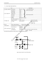
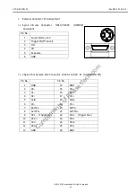
47pF
VD,HD
Exposure Output
+5.0V(VCC)
Trigger Input
HD74LV1GT32ACME
1K
Ω
100
Ω
470pF
(RENESAS)
Voh 3.8V (Min)
Vol 0.55V (Max)
HD74LV1GT14 ACME
(RENESAS)
Vih 2.0V (Min)
Vil 0.8V (Max)
100
Ω
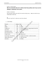
5.2.
Camera Output Signal Specification
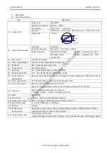
Item Specification
(1)
Video output data Video Output
640 (H)
×
480(V)
At Full Frame Scan Mode
(2) Sync. Signal I/O
LVAL output
LVDS
Camera Link connector
FVAL output
LVDS
DVAL output
LVDS
SP(Exposure) LVDS
HD output
LVTTL
6pins Circular connector
VD output
LVTTL
Exposure LVTTL
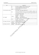
(3) Trigger input
Polarity POSI/NEGA
Selectable
Min width of trigger pulse 10
μ
s
Camera Link input
LVDS : CC1 input
Camera Link connector
TTL input
LVTTL: No.2 pin
6pins Circular connector
V
IH
Min. 2.0V
VIL Max. 0.8V
(4) Serial
Communication
SerTC
(Serial to Camera)
Camera Link input (LVDS)
SerTFG (Serial to Frame Grabber) Camera Link output (LVDS)
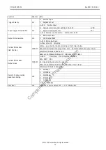
(5) Video output signal
White Clip Level
Digital 8bit
:FFh
Setup Level
Digital 8bit
:00h
Dark Shading
Digital 8bit
:under
±
04h for both vertical and horizontal.
(condition: gain 0dB)
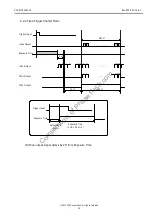
5 seconds shall be waited after turning on power to get proper camera operation.
6pins Circular Connector at rear: GPIO interface
Compliments
of
Phase1tech.com

