VCC-G20X30B
Rev. 900-731-31-00
©2012 CIS Corporation. All rights reserved.
12
1.8
μ
s
6.8
μ
s
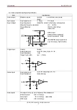
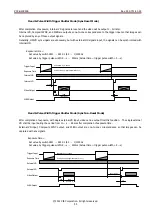
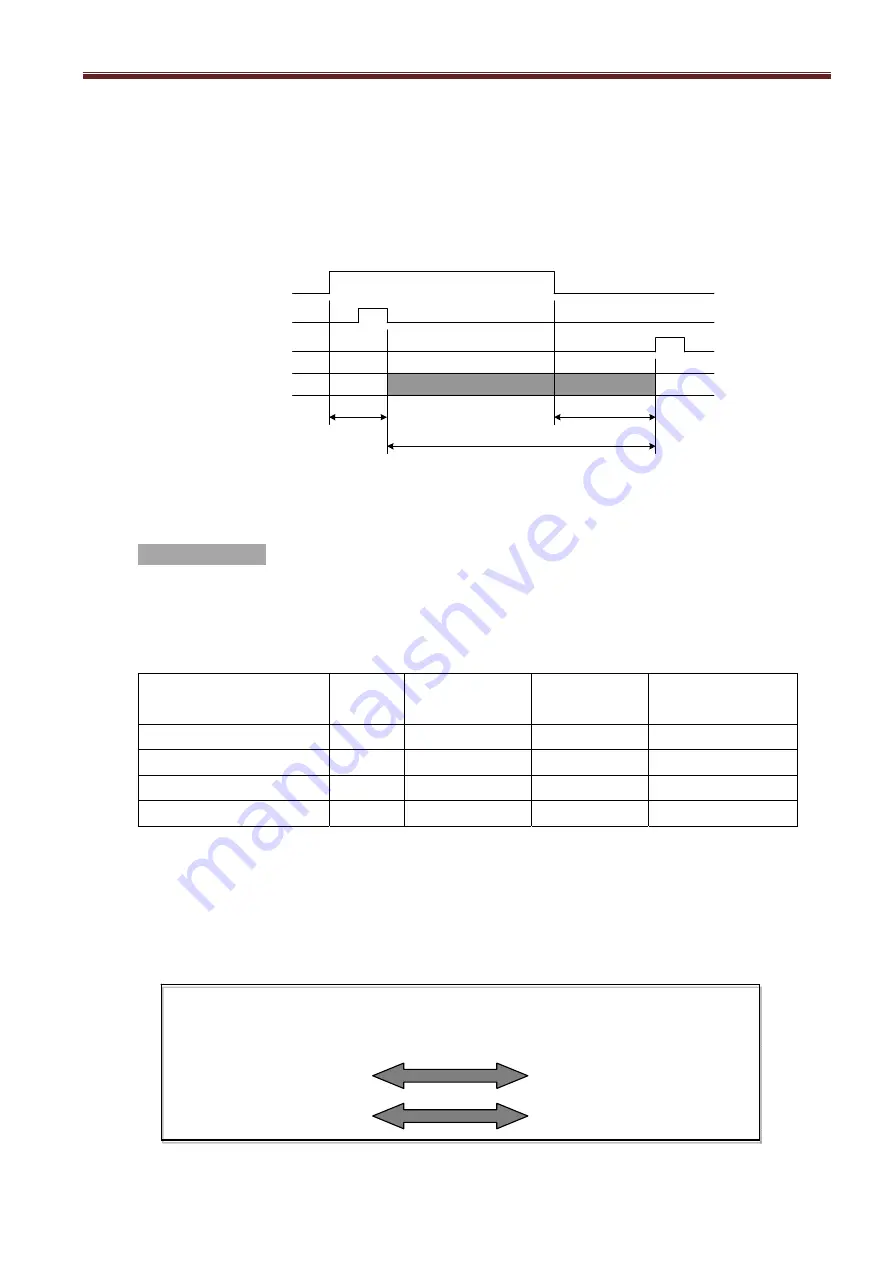
Exposure = (Trigger Pulse Width) + 5
μ
s
Trigger Input
Exposure Time
(Discharge)
(Readout)
Caution 1: When the next trigger is input before the completion of video signals output for the prior trigger, the
images could be improper.
Caution 2: Smear or blooming could occur when strong incident light is extensively illuminated, with setting the
electric shutter at high speed. To avoid this smear or blooming, lower the volume of incident light or use a
stroboscopic light source to control the light volume.
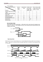
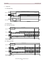
Caution 3: Please refer to the exposure timing chart below for the actual timing to start exposure after adding
trigger input, and for the actual timing to complete exposure at pulse width trigger shutter operation.
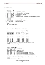
Scan Mode Settings
Scan 1
Scan 0
Setting Mode
SW9 SW4
OFF
OFF
Full Frame Scan Mode
OFF ON Binning
Scan
Mode
ON
OFF
1/2 Partial Scan Mode
ON
ON
1/4 Partial Scan Mode
Scan modes chart
Scan Mode
Frame
Scanning lines
Blanking Lines
Video output lines
(fps)
(Lines)
(Lines)
(Lines)
Full Frame Scan Mode
29.68
796
28
768
Binning Scan Mode
59.35
398
208
370
1/2 Partial Scan Mode
59.35
398
33
348
1/4 Partial Scan Mode
118.7
199
38
136
Changing the scan settings
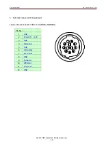
Scan settings shall be changed basically by the settings of camera switch SW9 and SW4 at rear, but it can be also changed
by the input level of No. 9pins of the circular connector.
However, please be noted that SW9 switch at rear and No.9pins (Partial IN) of the 12pins circular connector are in common
spec and either one shall be used. Please refer to the below for the truth value.
High Level (2.5
~
5V)
Low Level (Max 0.5V)
SW9: OFF and Partial IN:’H’
SW9: ON or Partial IN:’L’
At
SW4
OFF
Full Frame Scan Mode
1/2 Partial Scan Mode
At
SW4
ON
Binning Scan Mode
1/4 Partial Scan Mode


