background image

VCC-G20X30B 


     Rev. 900-731-30-00


©2012 CIS Corporation. All rights reserved. 

19 

10.


Cases for Indemnity (Limited Warranty) 


We shall be exempted from taking responsibility and held harmless for damage or losses incurred by the user in 
the following cases. 
 

z


In case damage or losses are caused by fire, earthquake, or other acts of God, acts by third party, deliberate 
or accidental misuse by the user, or use under extreme operating conditions. 


z


In case indirect, additional, consequential damages (loss of business interests, suspension of business 
activities) are incurred as result of malfunction or non-function of the equipment, we shall be exempted from 
responsibility for such damages. 


z


In case damage or losses are caused by failure to observe the information contained in the instructions in this 
product specification & operation manual. 


z


In case damage or losses are caused by use contrary to the instructions in this product specification & 
operation manual. 


z


In case damage or losses are caused by malfunction or other problems resulting from use of equipment or 
software that is not specified. 


z


In case damage or losses are caused by repair or modification conducted by the customer or any unauthorized 
third party (such as an unauthorized service representative). 


z


Expenses we bear on this product shall be limited to the individual price of the product. 


11.    CCD Pixel Defect 

After delivery, on the rare occasion, CCD pixel defects might be noted with time of usage of the products.     

The cause of the CCD pixel defects is the characteristic phenomenon of CCD itself and CIS shall be exempted 

from taking responsibility on it.     


12.  Product Support 

When defects or malfunction of our products occur, and if you would like us to investigate on the cause and 
repair, please contact your distributors you purchased from to consult and coordinate.   


Summary of Contents for VCC-G20X30B

Page 1: ...VCC G20X30B Rev 900 731 31 00 2012 CIS Corporation All rights reserved Analog I F 29mm Cubic XGA Analog B W Camera VCC G20X30B Product Specification Operational Manual CIS Corporation...

Page 2: ...PECIFICATION 7 4 3 CCD SPECTRAL RESPONSE REPRESENTATIVE VALUE 8 5 FUNCTION SETTINGS 9 6 EXTERNAL CONNECTOR PIN ASSIGNMENT 14 7 TIMING CHART 15 7 1 HORIZONTAL TIMING 15 7 2 VERTICAL TIMING 15 7 2 1 Ful...

Page 3: ...ation such as radio or TV transmitters Places subject to fluorescent light reflections Places subject to unstable flickering etc lighting conditions Places subject to strong vibration z Do not apply e...

Page 4: ...put are valid 1 60s 1 10 000s 8 steps fixed shutter speed can be set by rear switch 9 s 250ms shutter speed can be set by pulse width trigger shutter mode Restart Rest mode to enable long time exposur...

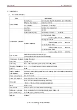
Page 5: ...Hz Sync system Internal sync HD VD external sync Internal External recognized automatically Video output standard Analog VS output Resolution 768 TV lines Sensitivity F5 6 400 lx Shutter speed 1 30s G...

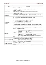
Page 6: ...N61000 6 2 2005 for Immunity To be applied to FCC Class A digital Device This device complies with Part 15 of the FCC Rules Operation is subject to the following two conditions 1 this device may not c...

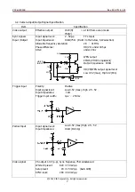
Page 7: ...ifference HD VD under 0 5 s Jitter under 20ns HD VD 75 10k SW 100 4 7k 33k 47pF 3 3V IN OUT CMOS 5V WEN output CMOS VHC04 equivalent Output impedance 100 HD VD WEN output signal level Low 0 5V max Hig...

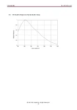
Page 8: ...VCC G20X30B Rev 900 731 31 00 2012 CIS Corporation All rights reserved 8 4 3 CCD Spectral Response Representative Value...

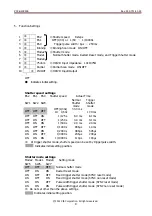
Page 9: ...s 33 3 ms Or 1 60s 17 0 ms OFF OFF ON 1 125 s 8 0 ms 8 1 ms OFF ON OFF 1 250 s 4 0 ms 4 1 ms OFF ON ON 1 500 s 2 0 ms 2 0 ms ON OFF OFF 1 1000 s 996 s 1 0 ms ON OFF ON 1 2000 s 489 s 505 s ON ON OFF 1...

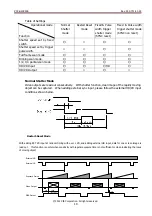
Page 10: ...r pulse width Full frame scan mode Binning scan mode 1 2 1 4 partial scan mode HD VD Input HD HD VD Output Normal Shutter Mode Video outputs are read out consecutively With shutter function clear imag...

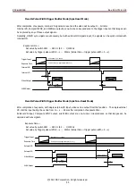
Page 11: ...ut so that images can be captured by any of those output signals Generally HD VD sync singals are unncessary but with external HD signals input the signals can be synchronized with internal HD Exposur...

Page 12: ...tings Scan 1 Scan 0 Setting Mode SW9 SW4 OFF OFF Full Frame Scan Mode OFF ON Binning Scan Mode ON OFF 1 2 Partial Scan Mode ON ON 1 4 Partial Scan Mode Scan modes chart Scan Mode Frame Scanning lines...

Page 13: ...rved 13 Changing 75ohm HD VD input impedance SW8 OFF HD VD input impedance 10k ON HD VD input impedance 75 Changing HD VD input and output SW10 OFF HD VD output ON HD VD input Internal External sync i...

Page 14: ...poration All rights reserved 14 6 External Connector Pin Assignment 12pins Circular Connector SNH 10 12 RPCB SAMWOO Pin No 1 GND 2 Power IN 12V 3 GND 4 Video Out 5 GND 6 HD In Out 7 VD In Out 8 GND 9...

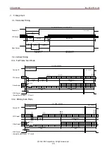
Page 15: ...7 9 779 Effective Lines Vertical Blanking Video Output Camera VD 11 2 1 778 779 28H Video Active Period 768H V 796H 29 68Hz 1H 42 33 s 2 10 12 77 WEN Output 1H Invalid Normal Shutter Mode H Level 7 Ti...

Page 16: ...nking Video Output Camera VD 214 567 33H Video Active Period 348H V 398H 59 35Hz 17 1H 42 33 s 220 219 High Speed Transmit WEN Output 1H Normal Shutter Mode H Level CCD Output High Speed Transmit Tran...

Page 17: ...29 The center of effective pixels shall be within f 0 6 to the center of lens mount Inclination of effective pixels Theta to datum plane shall be 0 5 Dimension from datum plane to the center of lens...

Page 18: ...Label Position 4 Mf 2 Depth3 3 Mf 3 Depth3 22 M2 Size 23 7 M3 Size 20 12 4 5 3 DC12V VS OUT MGC 1 4 7 10 MODE ON OFF less than 10mm C mount screws comply with ANSI ASME B1 1 1 32UN 2B Screw length fro...

Page 19: ...eration manual z In case damage or losses are caused by use contrary to the instructions in this product specification operation manual z In case damage or losses are caused by malfunction or other pr...

Reviews: