background image

BladeM LED Display System

Installation Manual

Cirrus | 200 West Rd, Portsmouth, NH 03801 | 877 636 2331 | [email protected] | cirrusled.com

20

This document is confidential & proprietary to Cirrus Systems for distribution to direct customers and their installers only.

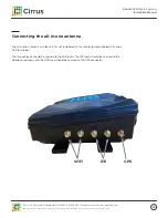
Connecting the all-in-one antenna

The all-in-one antenna has 5 leads, 2 for wifi (unlabeled), 2 for cellular (purple, labeled LTE), and a 

GPS lead (blue).

The two wifi leads should be secured to the WiFi posts, the LTE leads should be secured to the 

mobile connections, and the GPS lead should be secured to the GPS connector.

WiFi  

      LTE 


GPS

Summary of Contents for BladeM

Page 1: ...cirrusled com This document is confidential and proprietary to Cirrus Systems for distribution to direct customers and their installers only Copyright 2021 Cirrus Systems Inc All Rights Reserved Installation Manual The revolutionary and ultra high resolution BladeM REV04122021 ...

Page 2: ...uct storage 9 5 Warranty terms for all displays 10 B Frames and Assembly 13 Frame assembly 13 Frame mounting 14 Ventilation 15 C Electrical Section 16 Power cable 16 Power injectors 17 D Controller 18 M1 Pro Controller details 18 Mounting the M1 Pro Controller 19 Extension cables 19 Connecting the all in one antenna 20 Mounting the all in one antenna 21 M1 Pro indicator codes 22 Automapping proced...

Page 3: ...ed com cirrusled com 3 This document is confidential proprietary to Cirrus Systems for distribution to direct customers and their installers only 1 Equipment description 1 x2 Cirrus frame BladeM LED Displays are modular signs consisting of these components Frame bolts 20x0 5 1 x2 Legacy frame A Introduction Frames ...

Page 4: ...200 West Rd Portsmouth NH 03801 877 636 2331 contact cirrusled com cirrusled com 4 This document is confidential proprietary to Cirrus Systems for distribution to direct customers and their installers only Panel cable Rear view BladeM 9mm LED sign module ...

Page 5: ...contact cirrusled com cirrusled com 5 This document is confidential proprietary to Cirrus Systems for distribution to direct customers and their installers only To manage single and dual sided signs Controller box 10 Extension cable x2 Power cable M1 Pro Controller M1 Pro Controller mounting bracket ...

Page 6: ...1 877 636 2331 contact cirrusled com cirrusled com 6 This document is confidential proprietary to Cirrus Systems for distribution to direct customers and their installers only All in one antenna TP Link wireless kit All in one antenna Optional wireless access kit 10 Ethernet cable x2 ...

Page 7: ...mouth NH 03801 877 636 2331 contact cirrusled com cirrusled com 7 This document is confidential proprietary to Cirrus Systems for distribution to direct customers and their installers only optional may not be included Power injector Power injector Power cable Panel cable ...

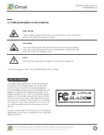
Page 8: ...rence at his own expense Changes or modifications to this device that are not expressly approved by Cirrus Systems Inc could void user s authority to operate this device Grounding It is essential to earth ground the sign before connecting controller Connecting signs that are not earth grounded may cause damage to the LED Display System and in severe cases cause death or injury Other Other safety m...

Page 9: ...ts should be subjected to immersion in water All deliveries shall be FOB Cirrus Systems Seller Portsmouth NH Methods and routes of shipment unless Seller specifies in writing otherwise shall be accepted as chosen by Seller at Seller s sole discretion Purchaser shall pay all costs of shipment Delivery to the carrier shall constitute delivery and passage of title to Purchaser and risk of loss shall ...

Page 10: ...discretion of Cirrus Systems Inc Coverage terminates if an end user sells transfers opens or tampers with any display system or its internal components What s covered Cirrus will replace any defective or malfunctioning part at no charge and pay for shipping All defective parts must be returned to Cirrus Systems for servicing upon failure Replacement components will be dispatched once a credit card...

Page 11: ... ESD precautions when handling Covered Products 07 Damage or problems caused by improper electrical grounding 08 Damage or problems caused by improper utility service 09 Damage or problems caused by use of non Cirrus supplied equipment or parts 10 Damage or problems caused by misuse abuse neglect or accident 11 Damage or problems caused by an external electrical fault or any unusual shock 12 Damag...

Page 12: ...ves any and all warranties whether express implied or statutory including all implied warranties of merchantability fitness for a particular purpose and non infringement Further Cirrus does not warrant guarantee or make any representations that any Software provided will be free from all bugs or that its use will be uninterrupted or error free Customer understands and agrees that Cirrus is not res...

Page 13: ...ir installers only 1 tall x 2 wide frames are assembled using the included hex bolts It is important to ensure that all frames are attached with the arrows facing front and up Four bolts should be used on each side of the frame and should be tightly fastened to ensure there are no gaps between the panels Two bolts will go in from one direction and two will go in from the opposite direction on each...

Page 14: ...or distribution to direct customers and their installers only Frame mounting One row of support mounting brackets not supplied must be attached for every four rows of frames Do not exceed four rows of frames without attaching an additional mounting bracket Mounting brackets should be attached for the entire horizontal length of the frames to prevent bowing or lateral stress Supports Required Here ...

Page 15: ...is required to keep the display within normal operating temperatures 40 70 C or 40 158 F Allowing natural convection by venting the top and bottom of the display is ideal Screen mesh or perforated material can be used to enclose the framing system Some examples of perforated materials Note Proper ventilation is a requirement for the warranty If top and bottom venting is not an option as in the cas...

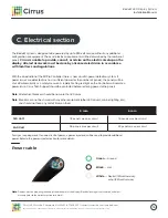
Page 16: ...d should not have any sort of timer on them Note Displays must be properly grounded at the breaker or at the display Electrical damage is not covered under our warranty refer to the warranty section for details Green Ground Black Hot White Neutral 120 volt service or hot 240 volt service For signs requiring more than one circuit of power a power injector s will be used to provide additional power ...

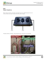
Page 17: ... Cirrus Systems for distribution to direct customers and their installers only Power injectors Power injectors are used in cases where a sign requires more than a single line of power Cirrus will advise on where to place power injectors as part of the pre install process The power injector has three ports one for the power cable a cable input and a cable output Power Output Input ...

Page 18: ...801 877 636 2331 contact cirrusled com cirrusled com 18 This document is confidential proprietary to Cirrus Systems for distribution to direct customers and their installers only M1 Pro Controller details Indicator light Power Port A Port B Ethernet WiFi Cell GPS Button D Controller ...

Page 19: ...a panel Note Do not use two extension cables connected together it may result in data loss and display issues Mounting the M1 Pro Controller The M1 Pro Controller is recommended to be mounted inside the sign to prevent unwanted access It can be placed outside but should not be mounted in direct sunlight The M1 Pro Controller should be mounted with the side with no ports facing up so no water can p...

Page 20: ...tems for distribution to direct customers and their installers only Connecting the all in one antenna The all in one antenna has 5 leads 2 for wifi unlabeled 2 for cellular purple labeled LTE and a GPS lead blue The two wifi leads should be secured to the WiFi posts the LTE leads should be secured to the mobile connections and the GPS lead should be secured to the GPS connector WiFi LTE GPS ...

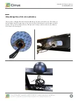
Page 21: ...bution to direct customers and their installers only Mounting the all in one antenna The all in one is designed to be fed mounted directly on the top or side of the sign The cables can be fed through one of the openings on the frame and then the locking nut secured down to hold it in place The rear of the antenna also has 3M peel and stick tape which can be used to adhere to the in place of the lo...

Page 22: ...onds Release when light turns green 3 green flashes followed by a pause for 10 seconds Network connection is active Initiate network test Press button once quickly 3 red flashes followed by a pause for 10 seconds Network connection is NOT active Initiate network test Press button once quickly Steady blue light Automapping complete test patterns will show for 2 minutes or until canceled To initiate...

Page 23: ...ontroller attempts to send mapping data to the panels Step 2 Once the automapping completes a system check is initiated The sign should show a panel map for 15 seconds then a network status for 15 seconds These will continue alternating for 2 minutes or until the Button is pressed once quickly Step 3 With our patented automapping technology new signs can be installed without even making a phone ca...

Page 24: ...y Cirrus BladeM panels are secured onto the framing system using 2 locking mechanisms The panels should fit only one way with the input and output port on the bottom of the panel The locking arms are controlled by the knobs on either side of the panel Front access The locking mechanism can also be accessed from the front of the display for service purposes using a 2 5 mm Allen wrench There is a sm...

Page 25: ...document is confidential proprietary to Cirrus Systems for distribution to direct customers and their installers only Connecting panels Each panel will have an input cable and an output cable except the last panel in the chain Each port should be labeled with the input on the right and the output on the left when facing the back of the panel ...

Page 26: ...ribution to direct customers and their installers only Cable connections 1 Align connector 3 Use thumb to twist lock into place 2 Grip heatsink with fingers to pull while pushing connector with thumbs This push pull method will avoid damaging the panel 4 Pull gently on cable to ensure lock is in place Using excess force when seating cables can lead to panel damage which will be present on display ...

Page 27: ...wing daisy chain pattern when connecting modules together When facing the back of the sign start at bottom left corner then go up to the top left then over one column then down to the bottom and so on When facing the back of the sign start at bottom right corner then go up to the top right then over one column then down to the bottom and so on Data port B Data Port A 3x6 wiring example Port A Data...

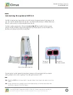
Page 28: ... the all in one antenna WiFi kit Optional The included WiFi kit pictured below is preconfigured and is intended to be plugged into the location s network to broadcast a CirrusLED WiFi network which our controllers connect to automatically Installation instructions are on page 30 Note The maximum distance between the wifi kit and the sign is roughly 300 and maybe less depending on the line of sight...

Page 29: ... and their installers only Both the Ethernet and WiFi kit have been preset to work with unrestricted access to the internet through the customer s network The default IP scheme is via DHCP In the case of a restricted network firewalls or static IP addresses additional configuration can be performed This is most easily performed before installation so reach out to Tech Support Important network inf...

Page 30: ...he WiFi kit box are the following components Not pictured but required for installation are 2 Ethernet cables We include 2 10 Ethernet cables as part of the controller kit but longer ones may be substituted if necessary Cat5 or Cat6 are both acceptable The maximum run for standard Ethernet is 300 Longer distances may be covered with fiber optic cable but must be converted back to standard Ethernet...

Page 31: ... PoE should be connected to a 120v outlet no more than 30 from the WAP An Ethernet cable connects the PoE to the WAP with one end plugged into the Ethernet port on the rear of the WAP and the other on the PoE port of the PoE unit see below The other port on the PoE labeled LAN should be connected via Ethernet directly into the customer s existing network switch router or gateway This cable length ...

Page 32: ......

Reviews: