


49
CS42426
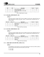
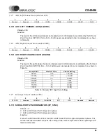
5.22.3 FUNCTIONAL CONTROL (FUNCTIONX)
Default = 00000
Function:
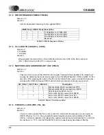
Mute Mode - If the pin is configured as a dedicated mute pin, then the functional bits determine which
channel mutes will be mapped to this pin according to the following table.
0 - Channel mute is not mapped to the GPOx pin
1 - Channel mute is mapped to the GPOx pin:
GPO/Overflow Mode - If the pin is configured as a GPO/Overflow Mode pin, then the Function1 and
Function0 bits determine how the output will behave according to the following table. It is recommend-
ed that in this mode the remaining functional bits be set to 0.
GPO, Drive High Mode - If the pin is configured as a general purpose output, then the functional bits
are ignored and the pin is driven high. It is recommended that in this mode all the functional bits be
set to 0.
GPOx
Reg Address
Function4
Function3
Function2
Function1
Function0
GPO7
pin 42
29h
M_AOUTA1
M_AOUTB1
M_AOUTA2
M_AOUTB2
M_AOUTA3
M_AOUTB3
Reserved
GPO6
pin 43
2Ah
M_AOUTA1
M_AOUTB1
M_AOUTA2
M_AOUTB2
M_AOUTA3
M_AOUTB3
Reserved
GPO5
pin 44
2Bh
M_AOUTA1
M_AOUTB1
M_AOUTA2
M_AOUTB2
M_AOUTA3
M_AOUTB3
Reserved
GPO4
pin 45
2Ch
M_AOUTA1
M_AOUTB1
M_AOUTA2
M_AOUTB2
M_AOUTA3
M_AOUTB3
Reserved
GPO3
pin 46
2Dh
M_AOUTA1
M_AOUTB1
M_AOUTA2
M_AOUTB2
M_AOUTA3
M_AOUTB3
Reserved
GPO2
pin 47
2Eh
M_AOUTA1
M_AOUTB1
M_AOUTA2
M_AOUTB2
M_AOUTA3
M_AOUTB3
Reserved
Reserved
GPO1
pin 48
2Fh
M_AOUTA1
M_AOUTB1
M_AOUTA2
M_AOUTB2
M_AOUTA3
M_AOUTB3
Reserved
Reserved
Function1
Function0
GPOx
Driver Type
0
0
Drive Low
CMOS
1
1
OVFL R or L
Open Drain


