


9
Instruction Manual
RGU-10, RGU-10C
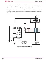
3.2.- INSTALLATION
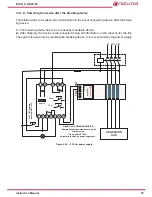
While the device is connected, the terminals, opening the cover or removing el-
ements can expose parts that are hazardous to the touch. The device must not
be used until the installation process is complete.
The device is installed on a DIN rail or on a panel (drilled panel 67
+1
x 67
+1
mm, according to DIN
43 700 using accessory). All connections must remain inside the electrical board.
3�2�1�- INSTALLATION OF DEVICE IN PANEL
A 72x72 mm front adapter accessory is used to install the device on a panel. All connections
must remain inside the electrical board.
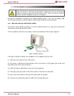
The front adapter accessory has a base, a frame two tabs and three screws,
Figure 1
.
Figure 1:Adapter accessory�
The steps to follow to perform the installation of the adapter accessory are:
1�-
The base is mounted on top of the device.
2�-
The device is attached by screwing the holes in the device on the upper right corner and
lower left corner on the front of device.
3�-
The front frame is attached to cover the mounting points.
4�-
Three green pressure tabs on the side runners of the base are attached.
5�-
The device is mounted in the hole in the panel with the adapter.
6�-
The tabs run towards the panel to obtain the mounting pressure.
Summary of Contents for RGU-10
Page 1: ...INSTRUCTION MANUAL Electronic earth leakage protection relay RGU 10 RGU 10C M98203201 03 18A ...
Page 2: ...2 RGU 10 RGU 10C Instruction Manual ...
Page 43: ...43 Instruction Manual RGU 10 RGU 10C 10 CE CERTIFICATE ...
Page 44: ...44 RGU 10 RGU 10C Instruction Manual ...